
You are using an out of date browser. It may not display this or other websites correctly.
You should upgrade or use an alternative browser.
You should upgrade or use an alternative browser.
Placing immersion heater on standalone circuit
- Thread starter Sard
- Start date
If that one socket is a spur from a ring you cannot add another spur to it.Thank you, this is very helpful. In terms of adding a circuit for loft sockets, could I just wire in one socket into the loft for now and run a fused spur for the boiler from there.
If that one socket is a spur from a ring you cannot add another spur to it.
I meant this in the context of a new circuit i.e. could I just have one socket and a fused spur and the ring could be extended appropriately when the loft is converted
If you want One socket up there then run a Spur and at a later date you can indeed split the Ring. If you're able to run one cable to the loft from your DB you could just have a Radial up there either 4mm or 2.5mm depending on what your powering.
The reg on non combustible CU is not retrospective so no need to change it.
One sparky that I enquired with said that it's not compliant to add new circuits to these types of boards?
When sparkies come out with these pearls of wisdom ask them to quote the actual reg number and to show you in their copy of the regs.One sparky that I enquired with said that it's not compliant to add new circuits to these types of boards?
Last edited:
- Joined
- 22 Jan 2007
- Messages
- 24,026
- Reaction score
- 3,548
- Country

When sparkles come out
That did make me chuckle
If you want One socket up there then run a Spur and at a later date you can indeed split the Ring. If you're able to run one cable to the loft from your DB you could just have a Radial up there either 4mm or 2.5mm depending on what your powering.
Thank you, having researched it, I will place a new radial circuit in the loft to power future sockets.
When sparkles come out with these pearls of wisdom ask them to quote the actual reg number and to show you in their copy of the regs.
Lol ok, that clears that up then!
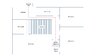
One other bit of advice i'd like is the proposed route of the wiring. I've mocked up how I think it will go and mindful of safe zones. I've drawn where the CU sits on ground floor and the route under the floor boards and then up to the loft via the airing cupboard. The airing cupboard is a tricky one, as the wires will most likely have to sit on the drywall in a safe zone and enclosed in the some trunking. I will also place the Immersion heater switch in the airing cupboard.
Could anyone advise if this is suitable given the type of cables I will be running through there? Lastly, is there a minimum distance that should separate central heating pipes from the wires under the floorboards?
Could anyone advise if this is suitable given the type of cables I will be running through there? Lastly, is there a minimum distance that should separate central heating pipes from the wires under the floorboards?
Attachments
- Joined
- 17 Aug 2010
- Messages
- 2,888
- Reaction score
- 506
- Country
Not sure exactly what you mean about safe zones in the airing cupboard. Visible wiring or wiring in visible trunking does not need to be in a safe zone.
Now edited.That did make me chuckle
Not sure exactly what you mean about safe zones in the airing cupboard. Visible wiring or wiring in visible trunking does not need to be in a safe zone.
oh ok, I was trying to explain that the wiring will be in the corner

Normally there will be an existing cable route from the CU upto the loft (e.g for lights cable). It maybe worth exploring this first. (could be less effort - I dunno)
Doesn't help with you wanting the switch in the airing cupboard. You could always run a T&E down from the loft for switch. or put the immersion switch next to the CU
Mine seam to run near a bedroom light switch. (kinda in a safe zone).
Looking in the loft, you can sometimes get an idea of where a chunk of cables go down
Normally there will be an existing cable route from the CU upto the loft (e.g for lights cable). It maybe worth exploring this first. (could be less effort - I dunno)
Doesn't help with you wanting the switch in the airing cupboard. You could always run a T&E down from the loft for switch. or put the immersion switch next to the CU
Thank you for the input. I have considered the existing route but it would involve a lot of destruction to locate and feed cables through, which is not an option for me. Previosuly the cylinder was in the airing cupboard but it was recently moved to the loft, so my filling loop, pressure guage, honeywell control unit and hive receiver still remain within the airing cupboard, hence the rationale for keeping the immersion switch there. Also if I'm not mistaken, some cabling would be required to run the full length either way from the CU to the immersion heater irrespective of where the switch is located, just the proportion of flex vs 4.5mm TE would change?
DIYnot Local
Staff member
If you need to find a tradesperson to get your job done, please try our local search below, or if you are doing it yourself you can find suppliers local to you.
Select the supplier or trade you require, enter your location to begin your search.
Please select a service and enter a location to continue...
Are you a trade or supplier? You can create your listing free at DIYnot Local