Problem with hive dual channel installation. Replacement from Drayton LP241

Joined
11 Dec 2023
Messages
13
Reaction score
6
Country
United Kingdom
Good evening. Recently i have installed Dual Channel Hive V3 thermostat replacing old Drayton LP241. I looked on the forums and that supposed to be straight swap.
However, i have problem. At the moment when i will put hot water on, radiators get hot. Heating can be disabled but radiators will still get hot.
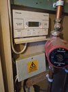
I have tracked the problem to probability of faulty motorized valve or its head which will be replaced. Changing temperature down on the programmer will not stop the heating.

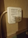
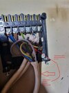
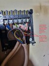
Another thing is wiring. There was wireless thing with the room programmer connected to Drayton which i have removed and disconnected the wires from the Drayton mounting plate. Disconnected doubled live and neutral and the left over wire i have connected to terminal labeled 4 in Drayton mounting plate which i assume is Central heating on. Is that correct place for this wire?

Setup is:

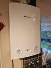
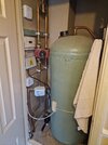
Worcester Greenstar 18Ri Erp boiler with hot water tank
3 way Drayton motorised valve
Hive V3 Dual channel thermostat

I know that motorized head was replaced before and was not connected by the professional. Is it only 4 wires supposed to be going to drayton mounting plate or all 6? HW off NC and CH off NC on the plate dont have any wires connected. Unfortunately at the moment i don't have photo of junction box wiring.

Also i know that before fault heating could work only when hot water was on, is that problem with wiring or with valve position? On Which position valve should be set to get heating without hot water on? H M or W ?

Please help.
 

Attachments

  • 20231210_140245.jpg
    20231210_140245.jpg
    253.5 KB · Views: 66
  • 20231210_122001.jpg
    20231210_122001.jpg
    200.2 KB · Views: 65
  • 20231210_123557.jpg
    20231210_123557.jpg
    241 KB · Views: 57
  • 20231210_123606.jpg
    20231210_123606.jpg
    241.2 KB · Views: 62
  • 20231202_175708.jpg
    20231202_175708.jpg
    210.5 KB · Views: 73
Last edited:
Sponsored Links
You are right, the Drayton and Dual Channel Hive do have the same backplate and connections.

Drayton LP241
lp.JPG


Hive.JPG


To decommission the old thermostat, assuming that this is as the BDR91 receiver was originally installed and working:

123.jpg


1. The two blue wires in N should remain connected together

2. The two brown wires in L should remain connected together

3. The wires in 1 and 3 should be joined together.
[a green/yellow wire shouldn't really be used for a live connection but it happens sometimes with lazy installs]

This is the easiest way for DIY, but if you are electrically competent, the cables can be traced back to their origins the changes made there.
 
The double blue and double brown now are a single wires as the wirelless thing was connected there and i have removed it. So there is now one blue, one brown, and also 1 blue wire connected to 3 and the remaining green and yellow wire i have connected to 4. So what exactly i need to rearange?? Is 1 and 3 needs to be bridged?? What about 4?? Would you be able to draw some schematics?

Will take pic of the junction box and the plate this evening, maybe this will help to trace wires and help me to connect it properly.
So now question is if I wired the hive correctly. I left Live, neutral and no.3 as it was, only the wire which was connected to wireless switch i connected to no.4. Not sure if i have gravity feed or pumped system. There is cold water tank in the loft however there is also a pump next to the hot water tank.
 
Last edited:
The double blue and double brown now are a single wires as the wirelless thing was connected there and i have removed it.
If I have understood you correctly and you have separated the two N and two L wires, you may have created a problem. Often there are two sets of wires connected to the receiver. As well as providing the power supply to the wireless receiver, another set of wires often go off to supply another part of the system (for example: boiler/wiring centre/programmer). The diagram below represents the sort of thing I mean and does not necessarily represent your system, it's only to illustrate why there may be are two wires in each of the N and L:

abc.jpg


So, if you have separated the wires and not rewired it elsewhere to take this into account then you may have created an open circuit. If you have rewired it to take into account then you can ignore this.

Will take pic of the junction box and the plate this evening, maybe this will help to trace wires and help me to connect it properly.
This can be difficult as there is no set wiring colour code and the method of installation will vary according to the wiring materials used, the personal preferences of the installer, if the system has been modified at some point, and the layout of the property. Unless it's possible to know where each of the wires leaving the wiring centre is connected at their other end, it can be difficult to work out.

Probably the easiest way if you don't know what each wire does and how the whole system works together as a whole, would be to put it all back as it was and confirm that everything is working as it should [including changing the motorised valve if it is faulty] Once you know it is all working as it should do, then to convert it to Hive by:

1. Exchange the Drayton for the Hive Dual Channel

2. Replace the wireless receiver with a junction box and put the two blue wires from N in one terminal, the two brown wires from L in another terminal and the wires from terminals 1 and 3 in a third terminal.
 
  • Like
Reactions: CBW
Sponsored Links
Blue and brown wires disconnected were only to power wireless receiver. There was one cable coming from the wireless receiver with 5 wires inside (Brown, Blue, Black, Yellow green, Grey). Grey wasn't connected anywhere, Blue and Brown - Neutral and Live on Drayton mounting plate, Earth was connected to earth on Drayton mounting plate and Black was connected to terminal block to join the cable with the brown wire coming out of the same cable as which the blue wire is connected originally to no.3. So what I did is after removing the wireless receiver I only had one brown cable left which I have connected to no.4 assuming this is heating on. So after removing the wireless receiver can i just bridge 1 and 3 in the Drayton mounting plate instead putting another junction box?? Is this not by any chance bridged already in the wiring centre (as wasn't bridged before in the Drayton mounting plate) What about no.4 terminal on mounting plate? The wirelles receiver was managing heating on an off with wireless programmer so I assumed the left over brown wire must go to no.4 (heating on).
 

Attachments

  • 20231210_140245.jpg
    20231210_140245.jpg
    341.5 KB · Views: 37
Last edited:
I know that motorized head was replaced before and was not connected by the professional. Is it only 4 wires supposed to be going to drayton mounting plate or all 6? HW off NC and CH off NC on the plate dont have any wires connected. Unfortunately at the moment i don't have photo of junction box wiring.
You have a mid position valve so there must be a wire in the HW OFF terminal or it wont work correctly
 
  • Thanks
Reactions: CBW
2. Replace the wireless receiver with a junction box and put the two blue wires from N in one terminal, the two brown wires from L in another terminal and the wires from terminals 1 and 3 in a third terminal
Sorry @stem , you might be talking at cross purposes.
The image above is of the old Drayton/new Hive backplate.
The BDR91 has NL &. AB connections.
It appears as if the old Drayton was only switching H/W on and off through terminals 1 and 3.
Terminal 4 wasn't connected, as it was seemingly bypassed completely by the BDR 91.
Not sure if i have gravity feed or pumped system. There is cold water tank in the loft however there is also a pump next to the hot water tank.
You appear to have a Y plan system, this should allow independent control of the C/H and H/W.

Did you have a better photo of which wire was in the connection block, with the black wire?
And a photo of how you have currently wired the backplate?
 
You have a mid position valve so there must be a wire in the HW OFF terminal or it wont work correctly

There is a wire (YG) going to 1 which is HW off. I didn't touch this one.

Sorry @stem , you might be talking at cross purposes.
The image above is of the old Drayton/new Hive backplate.
The BDR91 has NL &. AB connections.
It appears as if the old Drayton was only switching H/W on and off through terminals 1 and 3.
Terminal 4 wasn't connected, as it was seemingly bypassed completely by the BDR 91.

You appear to have a Y plan system, this should allow independent control of the C/H and H/W.

Did you have a better photo of which wire was in the connection block, with the black wire?
And a photo of how you have currently wired the backplate?
Unfortunately i don't have better photos but i can mark on the current ones.
 

Attachments

  • 20231210_140245 (1).jpg
    20231210_140245 (1).jpg
    352.8 KB · Views: 32
Unfortunately i don't have better photos but i can mark on the current ones.
Ok, what colour wire was in the terminal block with the black wire? And did you put this wire into terminal 4?
Was it a brown?
 
Sorry @stem , you might be talking at cross purposes.
The image above is of the old Drayton/new Hive backplate.

Ah OK Thanks, yes of course, you're right. My mistake. I assumed the Drayton would have been correctly installed and terminals 3 and 4 would be used for the HW and CH, and that the backplate with wires in 1 and 3 which is often used with wireless receivers was the BDR91.

Anyway I'll butt out now and leave you to it. OP sorry for any confusion.
 
Yes, brown, connected to no.4 afterwards.
And the green/yellow in terminal 1 and the blue in terminal 3 haven't moved?
If so, it appears as if you have connected the backplate correctly :)

Also i know that before fault heating could work only when hot water was on, is that problem with wiring or with valve position? On Which position valve should be set to get heating without hot water on? H M or W ?
I don't know about the others, but this suggests to me that there was a pre-existing fault on the system - you should have been able to have independent heating and hot water with your 3 port valve.
 
And the green/yellow in terminal 1 and the blue in terminal 3 haven't moved?
If so, it appears as if you have connected the backplate correctly :)


I don't know about the others, but this suggests to me that there was a pre-existing fault on the system - you should have been able to have independent heating and hot water with your 3 port valve.
Yes. 1 and 3 not moved. Also as you say. Previously heating wasn't working without hot water on. Which would suggest gravity feed system but the mid position valve would suggest otherwise.. Hot water pressure in the taps is really low which would also suggest gravity feed.

I don't know about the others, but this suggests to me that there was a pre-existing fault on the system - you should have been able to have independent heating and hot water with your 3 port valve.

So, how this would have to be rewired? I will take some better pictures this evening including wiring central.
 
Last edited:

DIYnot Local

Staff member

If you need to find a tradesperson to get your job done, please try our local search below, or if you are doing it yourself you can find suppliers local to you.

Select the supplier or trade you require, enter your location to begin your search.


Are you a trade or supplier? You can create your listing free at DIYnot Local

 
Sponsored Links
Back
Top