As I've just conceded to echoes, I think that I (and you) have been overlooking the fact that, in your scenario, the N-E fault current is travelling the 'wrong' way through the N side of the RCD - so I think it actually is true that the fault currents will add, not subtract.I don't think so. I think they will balance. keep in mind that the N-E 5Volts (and the subsequent 5mA that you mention) is not from the phase.
It is from the Neutral via the sub-transformer so it passes through the Neutral side of the toroid (to earth) just as the phase current (5mA that you mention) passes through the phase side of the toroid (to earth) Both sides of the toroid see the same current.
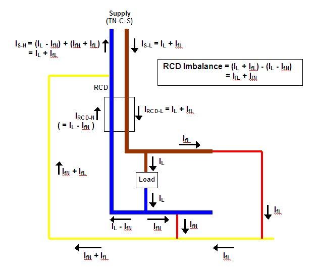
As for the TN-C-S situation I was thinking about throughout the early part of this discusion, I think the following diagram confirms that the fault currents again add (this time with current going the 'normal' direction through N sie of RCD):
Kind Regards, John.
 I knew that the phase issue would have got me in the end. Should have gone with my original thought about it which I immediately dismissed/retracted. Theres no substitute for sketching things out is there! But I still think there is still an open issue with TN-S/TT in a no load situation and will sketch it out later this evening.
")

")