RCD with non sin wave

Joined
27 Jan 2008
Messages
23,671
Reaction score
2,668
Location
Llanfair Caereinion, Nr Welshpool
Country
United Kingdom
Reading the stuff on RCD's it talks about type A, AC, and B and says:-
RCD type AC is the oldest type and it can only detect AC fault currents.
RCD type A is the most commonly used RCD type today. It can detect AC and pulsating DC fault currents, provided the DC fault currents cross or touch zero at least once in every 360° mains voltage cycle.
RCD type B is a new type. It can detect AC, pulsating DC and smooth DC fault currents.
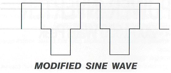
However the wave form shown does not look like this and I wonder how the three types will work with that wave form? This is what is produced by cheap inverters and because of steep sides will often fail to operate thyristor controls and also because of flat top does not have the peak voltage of a true sin wave some cheap meters will record it as being a low voltage although true RMS meters show correct value.

OK that's theory but what I want to know is practice. Has anyone had problems with RCD's with this wave form and does one really need to change any type AC RCD's or in practice will they still work? If changing what type is required? As far as I can tell type B are quite rare Siemens and ABB make them but this would likely require a consumer unit change and although a distribution unit can be used where I am looking now as the system is under continuous control of a competent person in other cases one is likely to only be able to fit a type tested consumer unit and invariably these are supplied with type AC already fitted.

So has anyone tested a type AC with an inverter supply and did it trip OK? i.e. is there any real need to worry? Once inverter is fitted we can test of course but likely to be on a Sunday so prior knowledge would be handy.
 
Sponsored Links
Does the inverter have a N-E link in it? If not then an RCD is next to useless anyway,
Re. the modified sine wave - if you fire it through a 1:1 transformer you should get a more normal sine wave out.
I wouldn't like to trust a normal AC RCD as they are reliant on the rate of change of current to operate - as the modified sine wave has flats at these points there is a chance it won't operate properly.
 
Thank you for your thoughts. Ensuring neutral and earth are bonded at the inverter is not a problem the system will be TN-S.

Two things come to mind. One my son's boat and two any other boat which I need to complete a PIR with.

I could just try with the test meter once fitted with son and likely I will but when tested others working out if modified or true on inverter is not always easy and most testing is done with sure power.

I was hoping some one else had already seen the problem and had tested but it seems I have to re-invent the wheel.

I agree with your thoughts but would like to see real results before telling anyone you can't use type AC with modified inverters.
 
All types of RCD should work OK with a MSW.

A Type A/AC is basically a balanced CT, so as long as the the current is alternating, it will induce a resultant current in the CT, it doesn't have to be a sine wave, just alternating and the transformer action will work,

But it will be interesting to see the results once you get the tester on such an installation.
:)
 
Sponsored Links
All types of RCD should work OK with a MSW.

A Type A/AC is basically a balanced CT, so as long as the the current is alternating, it will induce a resultant current in the CT, it doesn't have to be a sine wave, just alternating and the transformer action will work,

But it will be interesting to see the results once you get the tester on such an installation.
:)

Been there before, several times.
Operation of RCD is intermittant on MSW, even the manufacturer [don't remember which one] agreed.

*******s.

There's no reason why is shouldn't work, and until someone posts a real life situation in which an RCD failed to operate with a MSW supply, I would not worry about it. I don't have an inverter handy, but next time I encounter one I shall dig out an RCBO and whack the tester on it. However, it will trip just as it would on a perfect sinewave. Alternating current is alternating, the shape of the waveform don't matter. If it alternates it will induce.

(PS. I don't disagree that the manufacturers will not say their product will work on a MSW, but they will never stick their necks out and say their product will do anything more than is required to get the BS mark - 20A DP switches on a 32A circuit anyone?)
 
All types of RCD should work OK with a MSW.

A Type A/AC is basically a balanced CT, so as long as the the current is alternating, it will induce a resultant current in the CT, it doesn't have to be a sine wave, just alternating and the transformer action will work,

But it will be interesting to see the results once you get the tester on such an installation.
:)

Been there before, several times.
Operation of RCD is intermittant on MSW, even the manufacturer [don't remember which one] agreed.

****.

There's no reason why is shouldn't work, and until someone posts a real life situation in which an RCD failed to operate with a MSW supply, I would not worry about it. I don't have an inverter handy, but next time I encounter one I shall dig out an RCBO and whack the tester on it. However, it will trip just as it would on a perfect sinewave. Alternating current is alternating, the shape of the waveform don't matter. If it alternates it will induce.

(PS. I don't disagree that the manufacturers will not say their product will work on a MSW, but they will never stick their necks out and say their product will do anything more than is required to get the BS mark - 20A DP switches on a 32A circuit anyone?)

View media item 22104 View media item 22105 View media item 22106 View media item 22107 View media item 22108
Some quick tests.
Robin always shows 7ms [2ms on other 1/2 cycle] as shown without RCD.
Trips at 300mA but does not at 100mA [or 30mA X 5].
Trips at 20mA on mains.
The other 1/2 cycle gave consistant results.

The real situation is slightly better, using a 2200 ohm resister [97mA when measured across the supply] it tripped but not at any lower current.
8100 ohm resister tripped it on mains.

Whole test repeated with another RCD which did trip at 30ma X 5 or 2400 ohm resister [91mA].
1363 plug labled R1+R2 is a N-E link.
Tests shown are using a 200W softstart MSW inverter, who's voltage is 274V on a Robin KMP 4120DL [loop tester], 445ish on a scope and 215 on a m/c meter.
A 900W MSW inverter gave worse results and a 400W true sinewave inverter gave results within a couple or so mS of mains even though its only 205V compared with my mains of 247V today [using Robin].

I hope this as interesting as I found it.
 
(PS. I don't disagree that the manufacturers will not say their product will work on a MSW, but they will never stick their necks out and say their product will do anything more than is required to get the BS mark - 20A DP switches on a 32A circuit anyone?)

The 20A switch should only be used on a 32A circuit if it contains [or preceeded or immediately followed by] a protective device rated no higher than 20A, ie a single 13A socket etc.

One of my gripes is ring final spurs using 2.5T&E for a double 13A socket.
 
Alternating current is alternating, the shape of the waveform don't matter. If it alternates it will induce.

Not entirely true, the magnetism induced is from the rate of change of current (di/dt).

In a true sine wave the voltage is constantly changing hence providing the current follows the voltage the induced magnetism will also be constantly changing.

In the modified waveform posted above the voltage jumps up and down and only changes a limited number of times per cycle. The resulting change in current hence magnetism isn't the same as a normal sinewave.

Another issue when something is used which isn't meant to be used on a modified waveform is that it may cause excess heat.
 
1363 plug labled R1+R2 is a N-E link.

Hi Sunray. Sorry to resurrect a really old topic, but im genuinely intriged and interested as to understand how this bit works. Could you explain it in a bit more depth at novice level please
:D
 
An RCD works by monitoring the current in the Live and in the Neutral. If these remain balanced the RCD will remain healthy.

Put simply, the N-E link is required as you need a path for current to flow back to the source of the supply when there is a fault which is not via the RCD thus causing an imbalance in the RCD and therefore the RCD to trip.

N-E links are common but not in your household wiring, your electricity company will have linked neutral and earth on their system prior to it entering your house, usually at their transformer. Sometimes they use the same conductor to bring N&E to your house (TN-CS).
 
Thanks Spark123, its how wiring one plug(R1=R2) (from the images) in a bank of sockets, did the trick.
I ask because ive posted another thread, as i want to recreate (and more importantly understand) how he got the inline rcd to work after the inverter.
my aim is to go - battery - inverter - rcd/fused spur - switching relay - lights circuit.

The relay not under load will revert the lighting circuit back through the rdc/mcb protected CU
 
It isn't ideal what he has done, it was just to prove a point between sparks. The bank of sockets is upstream from the RCD hence the N-E link was placed there as the N-E link.

Ideally the N-E link would be in the inverter as it is source of supply and ought to have an earth rod tying it down to mother earth. As you may find with small sources they are often left electrically floating or "separate".
 

DIYnot Local

Staff member

If you need to find a tradesperson to get your job done, please try our local search below, or if you are doing it yourself you can find suppliers local to you.

Select the supplier or trade you require, enter your location to begin your search.


Are you a trade or supplier? You can create your listing free at DIYnot Local

 
Sponsored Links
Back
Top