Replace Danfloss TP500 with Hive 2

Joined
28 Nov 2016
Messages
6
Reaction score
0
Country
United Kingdom
Hi,

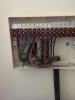
I am trying to replace my TP500 with Hive 2 however the wiring does not seem to line up.

I have no permanent neutral or heating off wire. Both of which are indicated as required in the Hive installation guide.

Here is my wiring behind the battery TP500
15224617_10155243871530110_1346036566_o.jpg


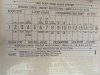
Here is the Hive install image

bg.png


I do no have N or 2.


Any advice would help.

Regards,
Ben
 
Sponsored Links
You need a permanent live too. You don't need a heating off wire.
What's that Danfoss wired into?
 
I assumed the grey wire was the live. I believe it is wired in to the multi zone valve system and on to the combi boiler.
 
Grey doesn't appear connected to anything and the blue sleeve would suggest it was originally intended to be a neutral.

One way or another you will need to do some rewiring to connect the hive up. Where the TP500 is, is where the wireless thermostat should go. The receiver ideally needs to be fitted either near the boiler or where the zone valves are if you have more than one for the heating zones.
 
Sponsored Links
These are the wires to the zone valves.

I was hoping I wouldn't have to get BG engineer out for the install due to 2 month wait! But thanks for letting me know it is not a simple plug in and go.
 

Attachments

  • 15225156_10155243940145110_1523362280_o.jpg
    15225156_10155243940145110_1523362280_o.jpg
    58.5 KB · Views: 314
Hive Multizone. So would install two receivers and two thermostats.
 
With multi zone you'd need to fit both receivers next to that wiring centre. The receivers act as the switch which your TP500 currently is doing.

You have all the wires you need there, you need a bit of 4 core wire for each receiver and a few wires need moving about.
 
Good news all wires are there.

I found the diagram on the back plate. Are you able to tell which numbers go to the N,L 1,2,3 connectors on the Hive receiver? FYI on my valve system there is a bridge between 2&3 and 4&5.

My guess is

Hive Diagram - Valve system

N (perm Neg) - UNSURE
L (perm Live) - 11
1 (Common) - 3
2 (Heating off) - NOT USED
3 (Heating on) - 6


The ground current goes in the the vertical terminal block.
 

Attachments

  • 15292878_10155243985470110_206342813_o.jpg
    15292878_10155243985470110_206342813_o.jpg
    156.1 KB · Views: 255
It hasn't been wired as per that diagram so ignore that.
Am i right in saying there are three wires in terminal 2?

If so then
2/3=Common to the TP500 and permanent live to the zone valves.
4/5=Neutrals
6=Switched live to boiler.
10/11=heating on wires to the zone valves.

Sooo...... for the hive you need to take a 5 core wire.
Hive L to 2 or 3
Hive N to 4 or 5
Hive 1 to 2 or 3 (if you wanted you could just put a link wire between Hive L and Hive 1 and just use a 4 core wire instead)
Hive 3 to 10 or 11 depending on which valve/heating zone its doing.

You then remove the wires from 2 and 10/11 that are currently wired to the TP500.

Id wire the first receiver in and pair it to a thermostat, then do the second receiver add that device to the hub then pair that up with thermostat.
 
Great. Many thanks for your help! Much appreciated.
 

DIYnot Local

Staff member

If you need to find a tradesperson to get your job done, please try our local search below, or if you are doing it yourself you can find suppliers local to you.

Select the supplier or trade you require, enter your location to begin your search.


Are you a trade or supplier? You can create your listing free at DIYnot Local

 
Sponsored Links
Back
Top