Replacing Polypipe P2CTC thermostat with HIVE wiring question

Joined
19 Nov 2022
Messages
20
Reaction score
0
Country
United Kingdom
Hello everyone,

I'd like to replace my DUAL channel Programmer made by Polypipe with HIVE mini receiver. I am not sure about the wiring.

The old polypipe programmer use 2 AA batteries.
HIVE use live wiring (N, L and Ground).
Here everything is clear.

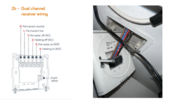
Polypipe has dual pairing:

C1 - Brown and Blue (Water)
C2 - Red and Black (Heating)


Hive has 1-4 wires.

1. Hot water OFF
2. Central Heating OFF

3. Hot water ON
4. Central Heating ON

How should I be connecting 4 wires:

1) BLUE
2) BLACK
3) BROWN
4) RED

or


1) BROWN
2) RED
3) BLUE
4) BLACK


Can someone help please? Would be grateful for any suggestions

Thank you so much in advance!
 

Attachments

  • Left(HIVE)_Right(PolyPipe).png
    Left(HIVE)_Right(PolyPipe).png
    947.1 KB · Views: 108
Sponsored Links
System boiler.

Polypipe PB2CTC programmer is connected to PB1ZM multizone unit
 
So you have :
1668871097523.png


How does yours compare..ie what have the wires r/b/bl/br been connected to at the wiring centre
 
Sponsored Links
That's the problem. I don't have access to the unit so i can't really check the cables.

I was just hoping that someone just by looking at the wire colours could tell what represents ON or OFF.


For instance if you look at CH1 (polypipe) you would think that BLUE - ON and BROWN - OFF
Or am i wrong?
 
I suppose I am trying to understand what you are trying to achieve as the PB2ctc is a clock programmer and the hive mini is a thermostat programmer.

You will need access to the wiring centre as you will need to wire in the hive receiver in place of the programmer and the thermostat. I am right in assuming that you want just the function of a time programmer from the hive and you don't want to use its primary function of thermostat ?
 
Yes, you are absolutely correct.

I simply want to be able to turn on the heating remotely. In such case HIVE receiver will act as programmer (turn on/off) and that's all.
In such scenario no rewiring is needed.

Current polypipe programmer does the same (except that is has a terrible interface). It only allows you to set the timer and that's pretty much it.

No need to have thermostat functionality (like setting up the temperature and etc).
 
So lets look at the hive...here is a bog standard heating solution

1668874888448.png

so the hive needs 240v supplied to it..... so the hive receiver switches on the boiler directly by switching the live via the 2 port valves - one on one off, two on or both off.

In your case do you have permanent 240v at the programmer ? ....I would suggest that the wiring centre is just sending a live down to the clock and that is being switched off or on . So that would be the first issue to get round.

The hive needs 240v to work as a switch. so you would need to provide 240v on one of those wires to the hive then send one of each wire back to the live side of the wiring cntre. at the moment the pb2ctc is just a remote switch for the wiring centre, so you need to isolate that function at the wiring centre. You need to access the wiring centre.....
 
Last edited:
in your case do you have permanent 240v at the programmer ?

-Yes, that's been solved. Works fine, paired with the hub and thermostat.
 
I would suggest that the wiring centre is just live down to the clock and that is being switched off or on.

- Possibly. Can't confirm whether it's live connected as i don't have access to it.

But what it has to do with the way programmer gets powered?
Original polypipe is 2X AAA batteries
HIVE as you rightly pointed out 240v permanent.
 
Ok so think about it, the original programmer just closes a switch at its end...according to the PB1ZM diagram you have the Time clock loop at the PB2ctc...two channels..each channel comes in from the feed and goes back to the live side ie it completes the circuit. - see the remove link if programmer attached label....so rather than 4 wires you need what...2 wires as you are no longer taking a feed from the wiring centre you are taking it from the hive....I would use a meter and work out what is the supply and what is the dead side , blank off the supply from the wiring centre and wire in the return only to the hive 3 and 4

Basically the hive switches the live feed it is given from the mains on 3 and 4 it energizes the circuit by giving terminal 3 or 4 a 240v Live from its 240v connection., the PB2ctc just acts a a light switch it provides no 240v live feed, it switches the wiring centres 240v live and hence only needs a couple of aa batteries to close a micro switch. Well assuming that the wirining center is actually sending 240v Live down to the programmer and does not have a 12v transformer in it....again a meter would tell you.
 
Last edited:
Thanks for the explanation.

Took me a while to digest.

PB2ctc just acts a a light switch it provides no 240v live feed, it switches the wiring centres 240v live and hence only needs a couple of aa batteries to close a micro switch.
- It obviously requires some voltage to run the display and basic logic of switching the feed.

Hive, switches its own given live feed. That's the main difference between these two.

Not sure why did they call it CH1 and CH2 then?
It makes no sense.

I would need to get a meter to test as it seems to be the only way to find out.
 
Well assuming that the wirining center is actually sending 240v Live down to the programmer and does not have a 12v transformer in it....again a meter would tell you.

- Your assumption must be right. Where else 240v would come from?
Or do you think it could be that PB2ctc sends 12v signal to PM1ZM where actual switch is taking place?
 
Why don’t you have access to the wiring center? I don’t know which wires are which as it’s not very clear and the manual seems scarce to non existent online.
 
Well assuming that the wirining center is actually sending 240v Live down to the programmer and does not have a 12v transformer in it....again a meter would tell you.

- Your assumption must be right. Where else 240v would come from?
Or do you think it could be that PB2ctc sends 12v signal to PM1ZM where actual switch is taking place?
could be 12v or might be 240v the schematic just says power supply.....

Ch1 and ch 2 will be wired in the wiring centre to turn on the boiler and move a diverter, but they just say its ok go...its the tank thermostat and the room thermostat that are in control of the boiler , you are turning them on to then take charge of the boiler... ..all you need to do is work out the voltage is it 12 v at the pb2ctc ? I would suggest 12v as the wiring diagram says black to the timer loop....solid black is normally 12v and all the rest are shown as green, brown blue. See they grey block bottom right in the wiring centre diagram..240v goes in then two black come out suggesting that this is a 12v power supply that is on the timer loop, this one being for a wireless room programmer.
 
Last edited:

DIYnot Local

Staff member

If you need to find a tradesperson to get your job done, please try our local search below, or if you are doing it yourself you can find suppliers local to you.

Select the supplier or trade you require, enter your location to begin your search.


Are you a trade or supplier? You can create your listing free at DIYnot Local

 
Sponsored Links
Back
Top