
My Scantronic 9800 operates 8 circuit zones. Circuit No 8 covers 3 Panic Buttons. Twice in the past week the alarm has been triggered while the system is unset and the remote keyboard shows code C8. Would be grateful for any advice on how to inspect each of the panic buttons to try and determine the problem.

You are using an out of date browser. It may not display this or other websites correctly.
You should upgrade or use an alternative browser.
You should upgrade or use an alternative browser.
Scantronic 9800 False Alarm
- Thread starter im2020
- Start date
Do they go back to the control panel on separate cables ? ….if so measure the resistance of each one ….post picture of all panic buttons
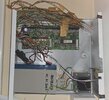
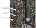
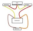
They go back to the control panel on separate cables but within the control panel is a connector that effectively links them together. The attached 3 images show this in detail. Can you advise on how to check resistances. Meanwhile, I don't think we've ever used/needed these Panic Alarms so might it be easier for me to just disconnect inside the contol panel?
Attachments
Remove one leg from the zone then measure each pair with a multimeter set on ohms ….if one pair is very high that’s possibly where the issue is
Thanks again. It's silly but I have to admit being flummoxed by what to do. Does remove one leg from the zone mean
remove either the red or yellow from the pcb on the panel or
remove one of the wires going into the connector or
remove one of the wires coming out from one of the Panic Attack devices?
And then do I measure each pair by connecting my multimeter to the leg I have removed and to each of the Panic Attack Devices themselves or to the other wires going into the connector or the pcb?
Remove the red connected to the pcb .. you will now have 3 pairs of wire ….starting at the red you disconnected and the connector block measure this , now measure at the two connector blocks , and finally the last connector block and the yellow still in the pcb
On a average cable run ( depending on quality of cable ) you a should be looking at 1- 3 ohms on each pair
No
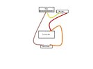
Well, I've measured the resistances and the red (that I removed from the pcb) to the connector block is 16 while the other two readings are 3. So would I be right in thinking it's the Panic Alarm at the front door that's causing the problem?
If so that's the one that we are never likely to use so I'd like to just take it out of the system.
Could I achieve that by simply removing the yellow for that PA from the connector and taking the brown from the back door out of the connector and into the pcb (where the red was)? That would now look like the attached picture.
Attachments
Yes
DIYnot Local
Staff member
If you need to find a tradesperson to get your job done, please try our local search below, or if you are doing it yourself you can find suppliers local to you.
Select the supplier or trade you require, enter your location to begin your search.
Please select a service and enter a location to continue...
Are you a trade or supplier? You can create your listing free at DIYnot Local