hello could somebody please explain to me how this would work, it is for two showers which are not supposed to work both at the same time, only one can be on at a time, thanks very much
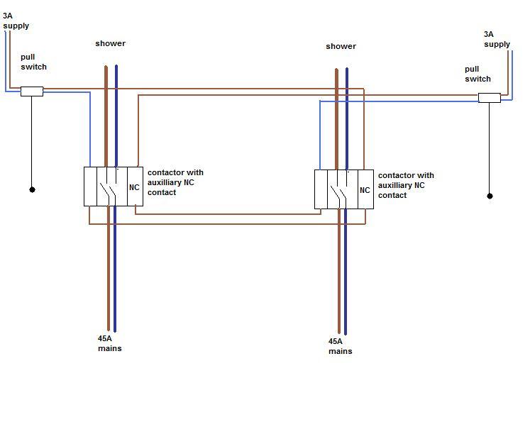
That system involves two contactors (fancy relays), with normally closed contacts on them. The supply may be from a single MCB, big enough to power either shower (40/45A), you dont need two circuits since only one shower can be used at once.
What the system ensures is that when one shower pullswitch is on, the other shower cannot be energised. It relys heavily on people turning off the pullswitch after use.
It also eliminates the need to cram big wires into ceiling pullswitches. Hurray!
In what context is your question? Do you understand how it works at all?
im just passed my electrician test, and i am really willing to learn and i have come on here to see what interesting things i can find and this diagram here was one, really interesting ye how it all works,
what was puzzling me was how it all worked from when somebody pulled the cords, does the n/c contact always stay closed, and when the cord is pulled does the engergise the coil and then returns on the neutral or how does it work how does it stop the other one working when one is on?
When the switch on the left is pulled on, the contactor closes the supply to the shower. The shower on the left can then be used.
Meanwhile the NC contact on the left has opened, thus cutting off the supply from the right switch to energise the right contactor, thus the right contactor cannot close.
If someone pulls the right switch while the left switch is on, the shower will not work until the left switch is turned off.
Someone pointed out a flaw in the design - if the supply was interrupted and then re-energised while both pullswitches were on, both contactors would be in competition to close first. They could end up "chattering". Some timer / delay device should be built into the circuit to stop this happening.
ah right!! i think i understand what you mean by this, so when the left switch is pulled on the contactor energises, so now the n/c contact is open cause there is power on it, so it wont shut until power has switched off on that contactor??
and is there a way of using contactors as well for emergency lighting like, when say, there a building with alot of lights, and obvisouly there would emergency lights there is a way of using contactors/relays i cant quiete remember?! and one emergency keyswitch to test all the lights at once! instead of having keyswitches in each room
how would u wire that up to do that any diagrams would be very good cheers steve gr8 help!
Strange you should mention that, contactors on lighting. I have just moved into a new workplace which has a master switch by the front door, and a master EM switch next to it. These switch a bank of 4 x 4 pole contactors. There are 8 circuits of lights, each circuits has 3 fittings with built in EM lighting. Therefore two contactors are needed for each circuit. 8 poles switch the permenant lives, and 8 poles switch the switched lives. The perm live ones are controlled by the keyswitch, and the S/L ones are controlled by the master switch.
Sadly I dont have diagrams, but I'd think it fairly straightforward.
They still managed to muck it up too. They got one circuit wired wrong, so the EMs came on when the master switch was off.
If you need to find a tradesperson to get your job done, please try our local search below,
or if you are doing it yourself you can find suppliers local to you.
Select the supplier or trade you require, enter your location to begin your search.
Please select a service and enter a location to continue...
Are you a trade or supplier? You can create your listing free at DIYnot Local