Strange IR readings......DOH!!

I foolishly did not note down the actual resistance readings being displayed when I did my tests (so calculated test current only on the basis of the nominal values of the resistors), but they were all pretty close. I'll do it again (without that oversight!) so I can determine precisely what current it's using.
OK, I've done it properly now. Because of the low precision of the display (to 0.01MΩ and 1V), I can only do it sensibly from 22kΩ upwards, and the results are summarised here:
As well as estimating the test current being used by dividing the displayed voltage by displayed resistance, in view of the precision issue, I've also estimated the upper and lower bounds of these estimates (by considering the worst possible rounding errors due to the limited precision of display).

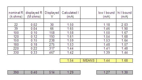
It is apparent that (whatever the manual may say about 1mA) my Fluke 1652 is using a test current of around 1.5 mA. As previously discussed, one would expect to hit a 'ceiling' at about 350kΩ - beyond which the test voltage could not increase any more and the test current would therefore reduce progressively as resistance increased above this value. I've included separate data for 390kΩ to illustrate that this 'ceiling'point seems to have been more-or-less reached by that resistance.

Kind Regards, John
 
Sponsored Links
Very interesting.

I am puzzled why in the specifications the test current is stated as -
1mA @ (test voltage)kΩ throughout the ranges.

I.e. with 500V setting the test voltage is 1mA @ 500kΩ
although in your results I suppose it would be 1.5mA @ 333k Ω.

Why is it so stated when it is 1mA (or 1.5mA in yours) all the time?
 
Very interesting. I am puzzled why in the specifications the test current is stated as - 1mA @ (test voltage)kΩ throughout the ranges. I.e. with 500V setting the test voltage is 1mA @ 500kΩ [although in your results I suppose it would be 1.5mA @ 333k Ω.] Why is it so stated when it is 1mA (or 1.5mA in yours) all the time?
Indeed, and similarly, for 250V testing, it says the test voltage is 1mA @ 250kΩ and for 1000V testing it says that the test voltage is 1mA at 1MΩ etc.

What it says is correct, but is only part of the story. When it says, for 500V testing, "1mA @ 500kΩ", what it could more usefully say is "1mA up to and including 500kΩ". If resistance rises above 500kΩ, since voltage cannot increase any higher (above ~500V), the current will then progressively decrease. However, throughout the range of resistances (from zero to 'infinity') dividing the actual voltage across the resistance by the actual current going through it will always give the value of the resistance (which presumably how the meter does its calculation) - for resistances up to 500kΩ, the current should remain roughly constant at ~1mA; above 500kΩ it will gradually decrease.

Does that help?

Kind Regards, John
 
I.e. with 500V setting the test voltage is 1mA @ 500kΩ
although in your results I suppose it would be 1.5mA @ 333k Ω.
Yes, that's how it seems. As I said, there seems to be a difference between my 1652 and the manual. It would be interesting to know what current yours is using. Do you happen to have a resistor somewhere in the range, say, 100kΩ to 330kΩ to hand? If so, if you measured it and noted the displayed resistance and voltage, dividing the latter by the former would tell you what current it's using.

Kind Regards, John
 
Sponsored Links
No, I don't have a resistor in the range.
Fair enough. Maybe next time you get an IR measurement under about 330kΩ (and ideally above about 50kΩ, in the interests of precision), you might try to rembember to note down the displayed resistance and voltage figures. We will then know what test current yiour machine is using!

However, if you're feeling experimental, you could try improvising. I've just tried with a 3" x 5" index card, soaked in tap water and then 'patted dry'. Across the long (5") axis of that, by pure chance, I get about 250kΩ. However, if you do that, be careful - 1mA or 1.5mA is not going to do you any harm, but the ~250V probably wouldn't feel very nice :)

Kind Regards, John
 
I've done that.

The results are in line with yours.

Could there be any internal workings which would give these results while actually applying the stated 1mA?
 
I've done that. The results are in line with yours. Could there be any internal workings which would give these results while actually applying the stated 1mA?
No. If putting a test current through a ~250kΩ resistance is resulting in ~375V across it, that's a test current of about 1.5mA. Full stop. (I've actually checked, using an independent meter, that the voltage being displayed by the Fluke really is the voltage appearing across the resistance being measured - and it is).

I think it's probably simply that the manual was written before the test current that the machines use was changed. How old is yoiur machine?

Kind Regards, John
 
I don't know how old it is as it was second hand.

The serial number is 9793062 if that gives a clue.
 
I don't know how old it is as it was second hand. The serial number is 9793062 if that gives a clue.
Mine was secondhand, too. I bought it about 4 years ago, at which time it had a calibration cert and sticker due to expire in late 2009, but that probably was not its first calibration. If the number on the sticker inside the battery compartment is the serial number, mine is 9183037, suggesting that it may be significantly older than yours.

This is all a bit odd. I've just looked at the manuals (both User Manual and Calibration Manual) for the 'current' 1653B/C and 1654B, plus supplementary manuals (basically corrections/changes) dated 2010/11. Those manuals look extremely similar to mine (apart from the 'new features') but all religiously stick to the 1mA test current for IR. The calibration manual indicates that checking the IR test current is not part of the calibration testng - they literally just test whether it gives correct IR results.

All a bit odd - I presume that others out there must have 1652s - I wonder what test current their's are using?!

Kind Regards, John
 
However, if you're feeling experimental, you could try improvising.
Wet card is good, Even better you can draw a resistor using a soft 2B pencil on paper. A thick heavily pencilled line with paper clips at the ends to make the terminals works quite well. Value too high then thicken the line. Value too low then make the line thinner by erasing some or move one clip further away from the other clip.
 
Wet card is good,
It worked very well for me, and I was incredibly lucky - my very first attempt got me a resistance bang slap in the middle of the range I was looking for!
Even better you can draw a resistor using a soft 2B pencil on paper. A thick heavily pencilled line with paper clips at the ends to make the terminals works quite well. Value too high then thicken the line. Value too low then make the line thinner by erasing some or move one clip further away from the other clip.
Yes, I've been knwn to do that, too. Mind you, with the damp card, one can snip away at the length or breadth until one gets the resistance one wants!

Kind Regards, John
 
Some where I had a photograph of a grid leak resistor and coupling capacitor created from pencil graphite on paper connected to a triode valve amplifying the audio from a crystal set. The capacitor plates being areas of graphite either side of the paper. From the good old days.
 
Some where I had a photograph of a grid leak resistor and coupling capacitor created from pencil graphite on paper connected to a triode valve amplifying the audio from a crystal set. The capacitor plates being areas of graphite either side of the paper. From the good old days.
Indeed, the good old days :) In a sense, we've almost turned a circle since, these days, one can create, simulate and test circuits 'on screen', without even needing a pencil and paper! Have have to say that, even gien the very high input impedance of the valve (essentially your grid leak resistor), I'm surprised that you managed to get enough capacitance from your bit of paper to get much audio through it - at best, not very good 'base response' I would imagine! At the other end of the frequency spectrum, my earliest playing with UHF circuitry routinely used very thin bits of mica (later PTFE) sandwiched between copper strips for decoupling, and sometimes coupling, capacitors.

Kind Regards, John
 
Returning to the topic of the thread, my demonstration (which I suppose I should have predicted) that IR testers use very low current constant-current sources begs the question as to the mechanism whereby IR testing at 500V (or 1000V) damages 'sensitive' electronic items.

On the face of it, such a tester should not damage anything (designed for 230-250V AC) unless its DC resistance (with the polarity of DC used by the tester) is very high, which I would have thought would not be the case with most electronic devices (many of which amount to a switched-mode PSU). There are obviously many ways of implementing a switched-mode PSU, but many of them would be expected to result in a relatively low DC resistance - certainly lower than the 167-250kΩ necessary for more than 250V to appear across the load with a 1-1.5mA constant-current source. A dimmer might be a slightly different issue but, with many designs, I would even have doubted that they would be susceptible to damage from a ~1.5mA constant-current source.

Any thoughts?

Kind Regards, John
 

DIYnot Local

Staff member

If you need to find a tradesperson to get your job done, please try our local search below, or if you are doing it yourself you can find suppliers local to you.

Select the supplier or trade you require, enter your location to begin your search.


Are you a trade or supplier? You can create your listing free at DIYnot Local

 
Sponsored Links
Back
Top