Texecom Premier 24

Its certainly doable, but I'm not sure if its worth it. If you can wire up an alarm system then you can wire up a mains doorbell. :D

If you do want to do it then a normal door bell push will work, something like the one in your link will be fine.

Sounds available from the panel are a bit limited: The chime sound can be played once, twice or three times when the bell is pressed.

If someone switches chimes off at the keypad then the doorbell won't sound so you may want to set area option 28- Auto Chime (C2A) and program all switches in Custom Output 2 stage A as Never Active and Inverted to ensure that the doorbell will always chime.

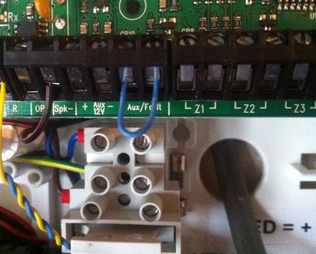
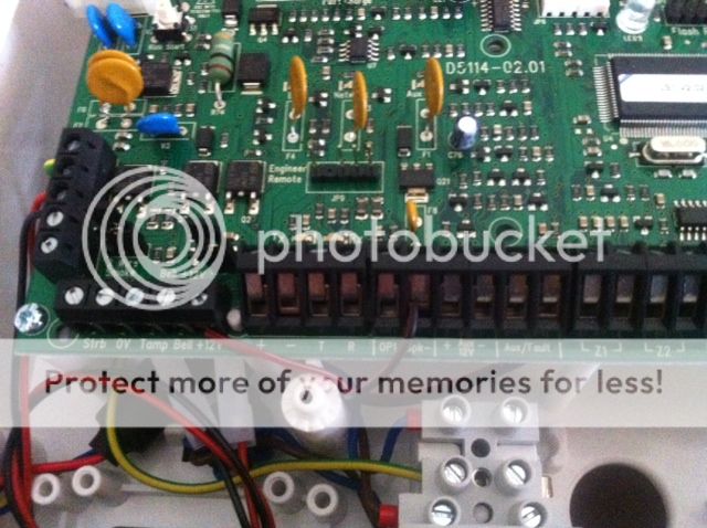
Try to wire the bell push to a zone in the panel, not a keypad or expander zone as the panel zones operate a bit faster and you may have a problem with a quick press and release of the bell not being noticed by the keypad or expander zones.

Don't use any resistors in the bell push.

Program the zone as: Type 19 - Custom, switch off all custom zone attributes, switch off all zone attributes 1, only select Quick Response on zone attributes 2, set wiring type as 1 - Normally open.

The doorbell will chime whether the alarm is set or not, if the doorbell is pushed when the alarm is set it will not cause an alarm but will give you a message on the keypad when you unset the system to say that the bell has been pushed.

Paul
 
Sponsored Links
Thanks Paul.
You're probably right in as much as it's most likely not worth it. I purchased a decent doorbell (wireless) last year, that more than suffices. If I'm going to have to purchase an expander (rather than using the free zone in the RKP) it's getting less worth the hassle by the minute. Also, everybody in the house quite likes (and is used to) the 'ding dong' chime we get with the Friedland (libra +)...so I'll put that idea to bed for a while :)

BTW...don't suppose you're an expert on coax cable too?? :)

Many thanks.
 
You could move one of the existing detectors to a keypad zone using that spare wire which you put in. That would free up a panel zone for the doorbell.

BTW...don't suppose you're an expert on coax cable too?? :)
No, sorry, but start a new topic and someone will help.
 
Good point...and you have a sterling memory too!

As for the coax - aye - I might do that. Not a real biggy and it's one of my other large projects that's nearing completion..just a few niggles. I'll try the electrics (computer?) forum for that.

Cheers.
 
Sponsored Links
Resistors: The ones with 3 red bands are 2k2. The ones with yellow, purple, red bands are 4k7. Or simply measure the resistance with a multimeter. If you haven't got a multimeter then get one and learn to use it, you will need it for fault finding on this installation.

Door contacts:
Your diagram is for wiring without resistors.
To use the resistors twist one leg of each resistor together and trap that twisted pair under one of the silver screws. The other end of the 4k7 resistor goes under the other silver screw together with one wire which goes back to the panel. The other end of the 2k2 resistor goes under any brass screw together with the other wire that goes back to the panel. Push the resistors so that they lie flat in the contact without letting the resistor legs touch any of the other screws. No soldering needed. The other end of the wires go into the two terminals for one zone in the panel. That's it, just two wires needed for the door contact, no power.

Hi - I've had the alarm panel fit put to one side whilst other things have been implemented (finished a drop of 300 metres CAT6 and 250 metres Coax!).

Just fitting the resistors to the surface contacts now. Seem a decent fit, though tricky to make sure the resistors don't touch the screws.

Is there a relatively geeky explanation as to what these resistors are doing in the dual end of line set up? Just curious really...feel as though I should know as I'm fitting them in.

Also - does it matter which wire (blue/yellow) connects to which resistor/screw?

Many thanks!

ps - all zones are now wired in, but I won't be wiring in the PIR's until the walls are plastered etc. Outdoor bellbox has wire ready to go through hole in wall, but 'very large ladder' required next week :)
 
Hello again :)

If the resistor legs are close to the screws you can slide a bit of sleeving over them (stripped off the alarm cable) if needed.

The 2k2 resistor lets the panel know that the door contact or PIR is there (no one has cut the wire or shorted the wires together).

The 4k7 resistor tells the panel if the detector is active or inactive (the switch is open or closed).

The panel will see a range of resistances:
0 - 2k = Zone Tamper (the blue & yellow wire are shorted together)
2k1 - 4k6 = Zone Secure (the 2k2 resistor is present and the 4k7 resistor is bypassed by a closed switch)
4k7 - 20k = Zone Active (the switch is open and the 2k2 + the 4k7 resistors are now in circuit)
21k+ = Zone Tamper (someone has cut the wire)

So when you have it wired correctly you should get a resistance of (about) 2k2 ohms when the door is closed and 6k9 ohms (2k2+4k7) when the door is open. You can test this with a multimeter before connecting the wires at the panel end.

Was that geeky enough?

It doesn't matter which way round the yellow/blue wires are, electricity flows through resistors & switches in either direction.

Pure 100% unadulterated geekery - love it!
Actually, that's a really good explanarion (you're rather good at that pcaouolte :) )

I'll post a pic of the contact some time today - one of the legs was touching an adjacent screw, but I've managed to shift this to one side. Good tip re the bit of cable strip - I'll cut a small section for any 'randy' legs to nestle into.

I did in fact use a multimeter to test those resistors...just to try it out really - all was fine :) About the testing the door contacts - test with door shut on the zone on the panel (one probe in each blue and yellow) and same when the door is open?

It's all but complete, but there's going to be a bit of a wait till it's active and I can start programming. Definitely pick up a cable and run it through the s/w. As I've laid a CAT6 cable in the panel up to the loft, I'll look at modem/ethernet in the future too.

Brilliant - thanks!
 
I did in fact use a multimeter to test those resistors...just to try it out really - all was fine :) About the testing the door contacts - test with door shut on the zone on the panel (one probe in each blue and yellow) and same when the door is open?
Disconnect the blue & yellow wires from the zone in the panel and put one meter probe on each. Resistance should be about 2k2 ohms with the door closed and 6k9 ohms with the door open. The resistance will be slightly higher on long cable runs.

You can do a similar test with a PIR but the PIR needs to have power from the panel while you are testing it.Disconnect the mains and run the panel on the battery whilst testing. Mains voltage can kill you. Take care not to short anything out in the panel whilst taking wires in and out of the zone connections if the panel is powered.
 
top man ,,,thanks for this posting ,,,much appreciiated ,,,easy as pie ..


Smokes:

Connect terminal A to one of the Zone terminals in the panel.
Connect terminal B to the other side of the same Zone in the panel.
Leave terminal C disconnected.
Connect terminal D to Aux -12v in the panel
Connect terminal E to Aux +12v in the panel
Terminal F can be left disconnected if you want the detector to reset when the smoke has gone.

Program the zone wiring for this zone as "normally closed".

Obviously its important to test these detectors when wired up and to make sure that you have loud internal sounders where they can be heard in bedrooms when you are asleep. Don't rely on the little speaker in the keypads to wake you if your house is on fire!

As I said I have never used these smoke detectors so test them thoroughly and if someone else with more knowledge comes along follow their advice in preference to mine!
 
Hey!
Believe it or not, due to ongoing refurb works in the house this alarm fit is still 'offline'!
I've carried out a rewire/carpentry/lighting/plastering/painting/decorating have knock this back somewhat (didn't do the skim!), but I'd like to complete the alarm fit this weekend hopefully!

I picked up the Dual Tech PIR (for the hall) last week and fitted that (slightly different wiring but think I've carried it out ok) and just one or two door contacts to finish. I've also purchased a PC-COM cable in order to do the programming (have visions of that being a bit of a pain, but I'll give it a whirl).

I'd also like to fit the PYRONIX alert speaker this evening, but struggling a little with the wiring.
I've attached a couple of pics from the instructions, but I'm not entirely confident of the connections?

pyronixnotes1.jpg


pyronixnotes2.jpg


As a guess:

12V+/- wire up to the 12v+/- on the panel (now in choc blocks as too many wires) one colour for the tamper and one for the alarm (again, unsure where these go on the panel)? Then an extra wire from the six core to the SPK connection on the panel (from the pyronix?) - removing the existing wire from the SPK which (again, I assume) is for the panel speaker (which I'd like to disable)?

I don't think this was covered on this extensive thread..and I'm kind of 'almost there' (give or take the programming). I recall the plan being to have this speaker used for the smoke alarms AND the alarm itself.

Here's a reminder pic of the panel (pre wired up) if it helps:

photo4.jpg


Hope pcaouolte still posts on here :eek: !

Many thanks.

[/img]
 
One core to bell +12 let's say red
One core to bell let's say blue
One core to L/S let's say yellow
One core to bell 0v let's say black
And green and white from tamper on the twin alert to aux/ fault
 
One core to bell +12 let's say red
One core to bell let's say blue
One core to L/S let's say yellow
One core to bell 0v let's say black
And green and white from tamper on the twin alert to aux/ fault

Thanks sparky - apologies but I'm still a tad confused though. Perhaps because I'm still thinking in the 'end of line' wiring I did with the PIR's and contacts (using four cores - +,-, Tamp and Alarm)?

Am I connecting the Pyronix to the Aux zone section 12v - 0v (the one full of the PIR +/- wires?) or the Bellbox section (STRB, 12v, 0v, Tamp, Alarm)?
The AUX/Fault is currently looped/linked with a short piece of cable (presume I don't need them?)
Not sure where/what the L/S refers to also - Light/Strobe (Strb on my panel?)

Just to clarify, I want to use the Pyronix to sound both the alarm and smoke alarms, but removing the panel alarm speaker (thus not giving it's location away in a 'scenario' - there's currently a wire connected to the SPK on the panel so I guess this is the alarm panel speaker?).

Many thanks!
 
L/S loud speaker ! The terminal that has the black wire in at moment
Yes use the bell box power for the speaker or the aux power any will do and the aux tamper on the panel as its spare and you won't be losing a zone.
 
L/S loud speaker ! The terminal that has the black wire in at moment
Yes use the bell box power for the speaker or the aux power any will do and the aux tamper on the panel as its spare and you won't be losing a zone.

Ah - loud speaker! I was looking for L/S on the panel :(

So I can use the Bell Power for 12v and 0v and also for the speaker (rather, if I wanted to, the panel speaker terminal - the one that is indeed currently wired in).
The pic of the panel above is before anything was actually wired in, so it's now full. The AUX 12v 0v has around 6 zones on there (hence resorting to choc block to fit in). The AUX/Fault (is this what you refer to as Aux Tamper?) is linked as in the pic below (advised to do that earlier in this thread - I'll be honest, I've forgotten why this has been done). Or are you referring to the Zones you can see on that pic (since used with the Alarm/Tamper connections)?:

alarmpanelauxfaultconnection.jpg


One core to bell +12 let's say red = Got that!

One core to bell let's say blue = 'Bell' on Bell box?

One core to L/S let's say yellow = Speaker - got that!

One core to bell 0v let's say black Got that!

And green and white from tamper on the twin alert to aux/ fault = need to clarify re loop/link.

I think I'm nearly there...and again, apologies for a raft of possible obvious questions!

Many thanks.
 

DIYnot Local

Staff member

If you need to find a tradesperson to get your job done, please try our local search below, or if you are doing it yourself you can find suppliers local to you.

Select the supplier or trade you require, enter your location to begin your search.


Are you a trade or supplier? You can create your listing free at DIYnot Local

 
Sponsored Links
Back
Top