Texecom Premier Elite 24 Wiring - Basics

Joined
30 Mar 2015
Messages
3,828
Reaction score
58
Country
United Kingdom
Hi All,

I've not wired one of these previously and have a question please. I've started small to keep things simple.

I've wired two keypads into the same set of terminals and then two PIR's in to separate zones. My PIR's are wired as below:
133465-185cb1ba06e5b015ee3024ab330b48d9.jpg


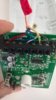
I am ignoring the Tamper wires for now.

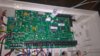
In my panel the + and - are wired into the shared power terminals and the blue and white cables are wired into their own zone (I am using zone 1 and 2). I couldn't see any significance in which of the two terminals the white and blue go into so I've opted for white in the right terminal and blue in the left.
133466-4d8e74dea1a5940fe413c48068e694b2.jpg

I'm running the system off battery currently.
This powers the keypads and PIR's. I've programmed the 2 zones (and set the others to not used) using mostly the default options and set the wiring to "normally closed" (as per advice from Texecom support) but when I do a walk test nothing is being detected.

I would greatly appreciate any advice that you can provide. Thanks in advance
 

Attachments

  • WP_20160911_15_22_12_Pro.jpg
    WP_20160911_15_22_12_Pro.jpg
    178.1 KB · Views: 725
  • control panel.jpg
    control panel.jpg
    285.6 KB · Views: 1,389
Sponsored Links
Suggestion : Remake your wiring connections into the control panel terminals. Especially the ones with two wires twisted together. As they are now is a problem waiting to happen.

If any are soldered, cut the solder off, and do as I have said. Soldering is un-necessary

Undo them, cut the ends of the wire to about 1.5 to 2ins, strip and tightly twist the bare wires together, then cut them short enough to go under the terminal clamps with no bits of wire showing.

Do it this way through out, you won't have any problems with short circuits then.

The colours how used do not matter, just be consistant, panel and zones.

It's a lot easier and quicker to connect the tamper circuits as you go. I doubt very much that you will connect them in the future, as said, easier and quicker to do it now.

It has always amaised me as to why DIYers always want to short circuit or leave out something that can and does get compromised.
 
thanks @Europlex. I should have said that the current connections are temporary as I want to get my head around the setup first. I plan to crimp these into the insulated connectors.

are you suggesting that the wiring is correct and the issue is the cables aren't pushed into the terminal properly? I think they are pushed in adequately but I can re-check of that's where you suspect the issue
 
What EOL jumper links are on in the pir ?
Can't see from the photo as it's cut short on the left hand side
 
Sponsored Links
NO, the issue is that the wires, be it one or two are not twisted tightly, making it look similar to it was before the insulation was removed to get them to make contact under the pressure plates at the terminals in the panel.

When done correctly NO wire should be showing outside of the terminal to which it is connected, or very little and I mean very little.

Temporary or not, always get into the habbit of doing it correctly, that is how short circuits are caused that could damage the detector/s or control panel.

Expense for being slap dash.
 
ive not changed the jumpers on PIR's. It will be the default of that helps?
 
thanks for your help @Europlex and I take your feedback on board. I absolutely agree with the calling discipline you are recommending and will follow this for sure. However, I'm unclear on whether this is the cause of my current issue. Is that what you are suspecting and is it consistent with the issue I am experiencing when attempting the walk test?

I am doubtful as I think there is enough contact between terminal and contact and also the wires twisted together are the power wires and I can see from the leds that both PIR's have power. I will check and amend this tomorrow but want to ensure that I am armed with all the necessary info before I tackle this tomorrow.​
 
Post picture of jumpers on the pir
If these ARE wrong you Will be going around in circles !
Plus it would be far better to wire as EOL as any tamper issues are better to diagnose ...
 
@sparkymarka here's a pic of the PIR and my reading of the manual suggests that unless you are using EOL, there is no need to adjust these. I think I'm using Normally Closed. Over to the experts...

in the meantime, I'm tidying the wiring in control panel as per suggestion.

look forward to your response.
 

Attachments

  • WP_20171228_08_46_28_Pro.jpg
    WP_20171228_08_46_28_Pro.jpg
    284 KB · Views: 625
@Europlex I've tidied up all the cables as per your suggestion but still get the same situation when attempting a walk test. It states "None". I am going to re-do these cables anyhow as I just want to get my head around the system first.

Is my issue with the config of a zone. Are there any simple steps I can follow to ensure this is correct? hanks for all your help.
 

Attachments

  • panel.jpg
    panel.jpg
    314.9 KB · Views: 2,788
To wire your pir EOL you need to put the little black jumpers on the correct resistor value in the pir .
Alarm 4.7 and tamper 2.2
Wire the pir with aux power red + black
2 wire pir with one wire in alarm outer one EOL and other wire tamper outer one eol the put that pair into your zone on the alarm pcb
 
Update: I made no change to PIR wiring or jumpers. Instead I set the "Remote Test" property to on for each of my two zones. Once this was done, I was able to perform the walk test. Onwards and upwards...

Thanks all
 

DIYnot Local

Staff member

If you need to find a tradesperson to get your job done, please try our local search below, or if you are doing it yourself you can find suppliers local to you.

Select the supplier or trade you require, enter your location to begin your search.


Are you a trade or supplier? You can create your listing free at DIYnot Local

 
Sponsored Links
Back
Top