Have been given a almost brand new treadmill (great!), only problem is it trips the electrics/blows the plug fuse, even before starting the thing up. I'm pushing my electronics GCSE to the max here and wouldn't mind a second opinion before I buy or even make a DIY DC motor controller or binning the thing full stop.
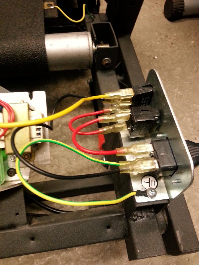
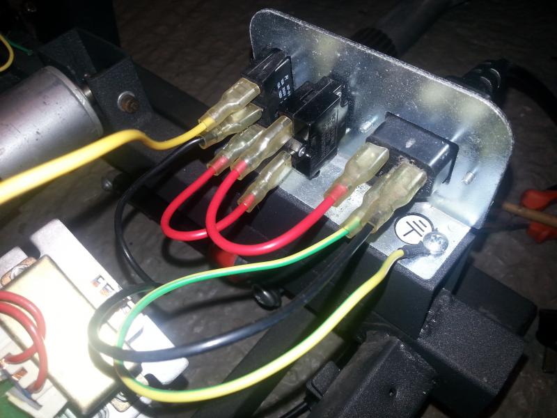
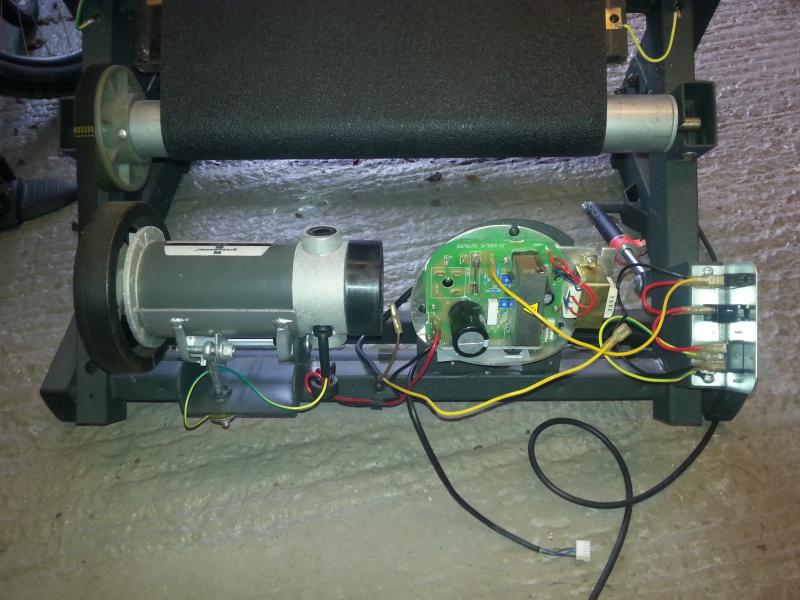
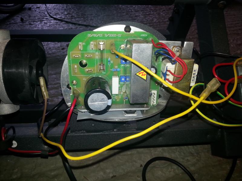
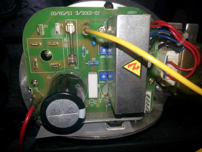
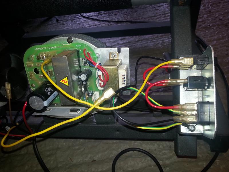
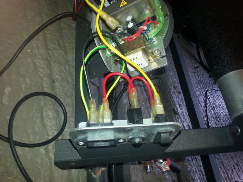
So my initial thought was to isolate the cause of the short so I tried three different power leads (kettle type), all three resulted in the electrics tripping. Next I disconnected the motor - no luck, then I disconnected the motor controller board - still shorting. At this point all we have is the electrical inlet, wired inline to what appears to be a overload reset button, then a switch. When I put the multimeter across the positive and negative terminal there appears to be a direct short when the switch is opened - certainly no or very little resistance is registered. This seems odd to me, but it doesn't look like anyone has messed with this. What I find odd is the fact that there is only one wire which links the 230V inlet to the board (yellow cable), this makes me think they must ground through the frame, although surely that wouldn't work with 230V.
Have attached a couple of pictures so help illustrate what I'm saying. My initial thoughts are go down the DC motor controller route, even making one as there are a few guides out there, but it would be nice to keep the display and controls which I'd lose with this. Have you come across anything similar before or got any suggestions?