
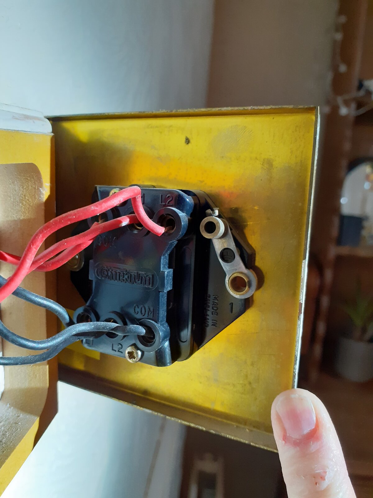
It’s a brass tube terminal which is attached to the back box. It’s less common for it to be in this position rather than the corner of the box but perfectly normal. It looks like the CPCs all terminate into it which is fine, although a link wire to the faceplate would be desirable.

You are using an out of date browser. It may not display this or other websites correctly.
You should upgrade or use an alternative browser.
You should upgrade or use an alternative browser.
Trying to install a double dimmer switch on weird wiring, please help
- Thread starter JosieJo11
- Start date
I think we are probably all agreed about that, but ...It’s a brass tube terminal which is attached to the back box. It’s less common for it to be in this position rather than the corner of the box but perfectly normal....
You must have good eyesight. I was (and remain) far from convinced about that, and now SUNRAY is also having doubts. How sure are you?.... It looks like the CPCs all terminate into it which is fine, although a link wire to the faceplate would be desirable.
Kind Regards, John
How sure are you?
90%
I'm saying there is a terminal and there is green/yellow sleeve which appears to end by the terminal. What I thought was the point at which the copper entered the terminal is not clear enough to say for certain whether it is terminated.I think we are probably all agreed about that, but ...
You must have good eyesight. I was (and remain) far from convinced about that, and now SUNRAY is also having doubts. How sure are you?
Kind Regards, John
However if I had to make a guess I'd err towards it being correctly terminated, which was my initial gut feeling.
I'm saying the same.I'm saying there is a terminal and there is green/yellow sleeve which appears to end by the terminal. What I thought was the point at which the copper entered the terminal is not clear enough to say for certain whether it is terminated.
If I had to, I would 'guess' the same - but guessing is not a very good idea!However if I had to make a guess I'd err towards it being correctly terminated, which was my initial gut feeling.
Kind Regards, John
I've taken more photos to show the wires better. I removed the labelling from all the wires yesterday once I'd changed them over but I've relabelled them exactly as before.
The way I wired the new dimmer was to copy across how the wires had been wired in to the old brass switch. For example the top red L1 I put into the top red L1 on the dimmer. John, I can see from your earlier post that this is incorrect. I was just so confused seeing 3 red and 3 black wires I was lost as it didn't match the wiring diagram that came with the switch!
Just to clarify, there is a yellow and green sheath that contains 3 copper wires, 1 from each grey cable and it is wired into the back box.
Also, I have bought an led dimmer, not a regular one.
Any further advice would be greatly appreciated. Thank you again!
Jo
Right. Thanks. As has been said, you should add a wire (with green/yellow sleeving) from that terminal in the back box (together with the existing wires) to the earth terminal on the switch, so as to reliably earth the metal plate of that switch.Just to clarify, there is a yellow and green sheath that contains 3 copper wires, 1 from each grey cable and it is wired into the back box.
Kind Regards, John
For a start your old switches had a combo of red and black in each one, you appear to have put ALL the reds in one dimmer and ALL the blacks in the other, so will obviously not work.
Clue, look at how and where the COM wires were on the old switches, each switch Left and Right has its 3 terminals laid out in a triangle NOT in line across the top
Clue, look at how and where the COM wires were on the old switches, each switch Left and Right has its 3 terminals laid out in a triangle NOT in line across the top
Last edited:
@JosieJo11 Though obviously not the case if you fit the new plastic dimmer as there is no needRight. Thanks. As has been said, you should add a wire (with green/yellow sleeving) from that terminal in the back box (together with the existing wires) to the earth terminal on the switch, so as to reliably earth the metal plate of that switch.
Kind Regards, John
Yes, sorry, I should have added that qualification - I was obviously talking about the situation 'as is'.@JosieJo11 Though obviously not the case if you fit the new plastic dimmer as there is no need
Kind Regards, John
Tut Tut John, i no what you meant, I had visions of Josie hunting for the earth terminal on the plastic switchYes, sorry, I should have added that qualification - I was obviously talking about the situation 'as is'.
Kind Regards, John
")
Indeed - and I'm sorry for introducing the confusion.Tut Tut John, i no what you meant, I had visions of Josie hunting for the earth terminal on the plastic switch
I could blame winston (not for the first time
) - since it was he who brought up the issue of the non-earthed metal faceplate (and maybe also, to some extent, RF who perpetuated my lack of attention, when he wrote "... a link wire to the faceplate would be desirable" Kind Regards, John
Any further advice would be greatly appreciated.
On your new, black, switch, I can't see the terminals, and I can't see the markings.
I expect each switch to have three terminals.
How are they marked?
DIYnot Local
Staff member
If you need to find a tradesperson to get your job done, please try our local search below, or if you are doing it yourself you can find suppliers local to you.
Select the supplier or trade you require, enter your location to begin your search.
Please select a service and enter a location to continue...
Are you a trade or supplier? You can create your listing free at DIYnot Local
Similar threads
- Replies
- 10
- Views
- 3K