
You are using an out of date browser. It may not display this or other websites correctly.
You should upgrade or use an alternative browser.
You should upgrade or use an alternative browser.
Two Way Switch
- Thread starter Xenophya
- Start date
Hello Again Chaps,
Firstly big thanks for all of the assistance it is very much appreciated because I am totally lost.
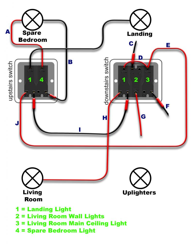
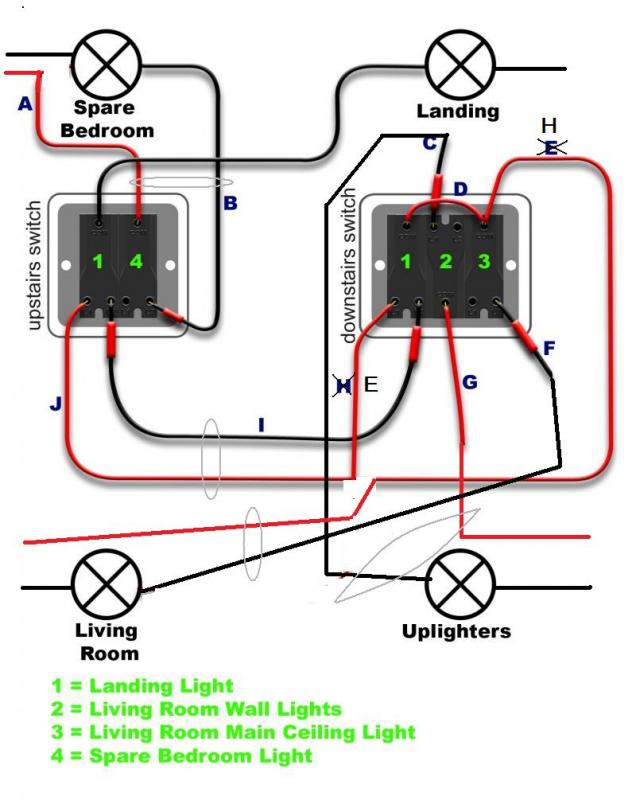
Ok I have, as suggested, removed the wire F which links the Com on switches 1 and 3. This resulted in the main living room light and and the landing light not working at all. The wall up-lighters and the spare bedroom light both still worked fine.
I then Disconnected I, B and G in the downstairs switch and checked each of them with the mains tester (with the power on obviously). B and I were both live (G wasn't). I should have checked to see if B remained live with 4 switched off upstairs but I forgot to before I had to make it all safe again and dash out to take the dog to the vets. It's too dark to look now.
I agree that it is odd that the spare bedroom light is outside of the room. It was like that when we moved in. I think that this is because there is no room on the wall next to the door (the boiler cupboard is there) and the other wall backs onto the shower. It may be worth mentioning again that the spare bedroom light is on the upstairs ring whilst the landing light is on the downstairs ring.
What should I try next??
Thanks Mark
Firstly big thanks for all of the assistance it is very much appreciated because I am totally lost.
Ok I have, as suggested, removed the wire F which links the Com on switches 1 and 3. This resulted in the main living room light and and the landing light not working at all. The wall up-lighters and the spare bedroom light both still worked fine.
I then Disconnected I, B and G in the downstairs switch and checked each of them with the mains tester (with the power on obviously). B and I were both live (G wasn't). I should have checked to see if B remained live with 4 switched off upstairs but I forgot to before I had to make it all safe again and dash out to take the dog to the vets. It's too dark to look now.
I agree that it is odd that the spare bedroom light is outside of the room. It was like that when we moved in. I think that this is because there is no room on the wall next to the door (the boiler cupboard is there) and the other wall backs onto the shower. It may be worth mentioning again that the spare bedroom light is on the upstairs ring whilst the landing light is on the downstairs ring.
What should I try next??
Thanks Mark
Can you please check the continuity of wire B?
B & J must be the other way round upstairs.
B & J must be the other way round upstairs.
Also, which wires are in the same cable, i.e. sheath.
- Joined
- 11 Jan 2004
- Messages
- 46,656
- Reaction score
- 3,895
- Country

Does the spare bed light work then?
Because the amended diagram suggests it will only work when the GF landing switch is in one of its positions.
Also, you may have made a mistake identifying the wires, as the spare bed light is fed from the same feed as the landing light according to the amended diagram and therefore both are on the same circuit.
In other words, if the spare bed light works regardless of the position of the GF landing switch and/ or the spare bed light stays lit when the fuse/mcb for the ground floor lights is out/off, then your diagram is sadly wrong.
Its time for a competent electrician
On site
You can't sort this over the wonderweb
On site
You can't sort this over the wonderweb
Hello again chaps,
Sorry for the delay in replying I have been at work all week and its too dark to do anything when I get it.
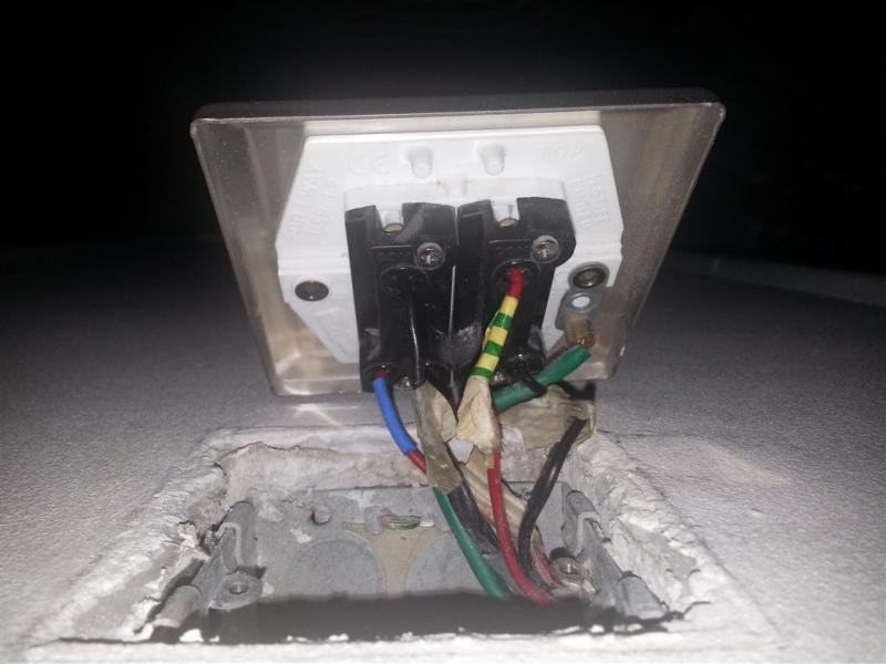
I spent all day yesterday trying to figure out what wires go where. I realised that in order for my test with the multimeter to check continuity to work I would need to ensure that the the wire I was checking was completely disconnected from the rest of the circuit not just at the switch. This is why I was getting false readings before because the wire was still connected at the light. I took photos and marked where all the wire currently go. Although they are not right I don't want to start changing anything until I have understood what is wrong.
I have uploaded photos for each of the main fittings and the switches. and my revised diagram of my findings. The diagram is now making more sense but I suspect it is still not right.
A and B now make sense as the switch for the spare room.
I ran out of time to check C & G which is why I have not shown them as connected (as I am learning assumption is the mother of all cock ups) but I am pretty sure they go to the Up-lighters as they work fine, and this would make sense.
F has me totally confused, it made continuity with a red wire in the upstairs landing light?? but with nothing else even when there were no visible wires connected. obviously it would complete a strange circuit if it went back to the landing light and would explain the switching behaviour if the live feed was coming from the living room light. What is F connected to in order to make continuity with a red wire?? Also why on earth would you wire it up like this?
You may be correct and it may be time to get a sparky in. But i'd like one last go at working it out myself.
Sorry for the delay in replying I have been at work all week and its too dark to do anything when I get it.
I spent all day yesterday trying to figure out what wires go where. I realised that in order for my test with the multimeter to check continuity to work I would need to ensure that the the wire I was checking was completely disconnected from the rest of the circuit not just at the switch. This is why I was getting false readings before because the wire was still connected at the light. I took photos and marked where all the wire currently go. Although they are not right I don't want to start changing anything until I have understood what is wrong.
I have uploaded photos for each of the main fittings and the switches. and my revised diagram of my findings. The diagram is now making more sense but I suspect it is still not right.
A and B now make sense as the switch for the spare room.
I ran out of time to check C & G which is why I have not shown them as connected (as I am learning assumption is the mother of all cock ups) but I am pretty sure they go to the Up-lighters as they work fine, and this would make sense.
F has me totally confused, it made continuity with a red wire in the upstairs landing light?? but with nothing else even when there were no visible wires connected. obviously it would complete a strange circuit if it went back to the landing light and would explain the switching behaviour if the live feed was coming from the living room light. What is F connected to in order to make continuity with a red wire?? Also why on earth would you wire it up like this?
You may be correct and it may be time to get a sparky in. But i'd like one last go at working it out myself.
Firstly, switch 2 is correct. Do not change
Wire A will come from the supply at the spare bed light, not the lamp.
Can you tell us which wires are in the same cable?
Wire A will come from the supply at the spare bed light, not the lamp.
Can you tell us which wires are in the same cable?
Your switch/wire diagram makes no sense at all. As stated before, you are leading yourself up and down many cul de sacs and getting nowhere.
I'm not sure how you are determining where these wires go to, but whatever method is wasting your time.
If your diagram is true then none of the lights would work.
Your diagram cannot work at all. eg
Spare bedroom. There is a lamp across the switch. But no live feed and no neutral anywhere.
Landing light on switch 1? are you SURE? There cannot also be the living room light connected at the other end.
Where does F go to?
Where are uplighters connected?
Wire J should be a live feed to the downstairs switch, but you seem to think it is a 2-way strapper to switch 1 - not possible.
I would advise you to put everything back as it was and to get an electrician with lots of patience to come on site and sort it out.
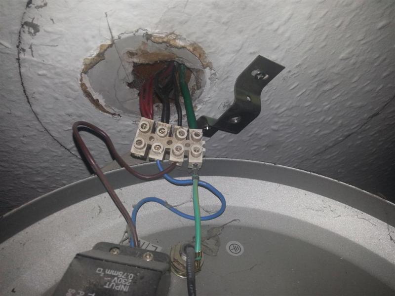
And which light is the bottom picture?Can you tell us which wires are in the same cable?
- Joined
- 11 Jan 2004
- Messages
- 46,656
- Reaction score
- 3,895
- Country
As things are at the moment, how many lights switch as they should?
Hello again, and again many thanks for the replies.
To answer your questions, all of the lights currently work and always have, I haven't yet changed any of the original wiring I have just been trying to work out what has been done before we moved in. The Spare Bedroom light currently works and switches exactly as it should, as do the Up-lighters in the living room.
The Living Room Light and the Landing Light both work but they are not switching correctly.
If the landing light was switched off up stairs it won't switch on without the living room light being switched on. If the living room light is switched on downstairs you can switch on and off both the living room light and the landing light with just the landing light switch. If the landing light was switched off upstairs it then works fine from downstairs but won't switch on upstairs.
As I described in previous posts to try and determine which wire is which I have been using a multimeter. This is not a new build so the walls are all already decorated so there is no way to physically trace the wires to see where they go. I have the meter dial set to the position for measuring resistance or continuity. I always test that the meter is working properly by touching the leads together (it is an audible one so I get a buzz). I then connect one end of the meter leads to a wire. I put the other probe into a connector attached to long length of wire essentially making one of the meter probes much longer. I then test to try and find the other end of the wire. If I have an open circuit across the pair of wires that I am testing then I know that can't be the same wire at the other end. I make sure that none of the wires are connected (so that there isn't a false reading) . Then I mark each wire with a piece of tape. This is the approach I would take if I were trying to find a stray wire on a motorcycle loom. I don't have any idea about how else you would do this (without x-ray vision). How would a professional electrician do this??
Whilst it still makes no sense I do feel that I have made some progress this weekend in trying to work out what is currently happening. I have not yet attempted to change anything.
I am now pretty sure that the diagram is correct for the wires going to and from the switches 2 & 4 (the ones for the spare bedroom light and the Up-lighters). To me at least these make sense and work as they should. I have not shown any of the other wires on the spare bedroom light because it all works and I don't think has anything to do with the landing light. If it wasn't in a double gang switch and there was room for it in the spare bedroom (so it didn't have to go on the landing) I wouldn't even have mentioned it. It is on the upstairs ring. The live feed and the neutral come from the bathroom.
Surely the first thing I need to do is identify which wire is which. If my method is flawed (which it could easily be as I've not been told that this is the right way to go about it) how would an electrician go about identifying which cable is which if nothing is marked?
Unfortunately I can't see the cable's sleeves so I don't know which wire is paired with which. I've tried pulling them out of the wall a bit further but they won't budge.
I do appreciate the help and constructive comments.
Mark.
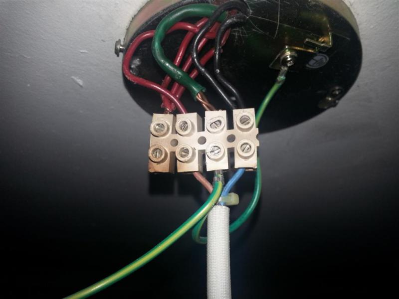
P.s. The light with the top hat shaped bracket (rather than the zinc cylinder) is the upstairs light.
To answer your questions, all of the lights currently work and always have, I haven't yet changed any of the original wiring I have just been trying to work out what has been done before we moved in. The Spare Bedroom light currently works and switches exactly as it should, as do the Up-lighters in the living room.
The Living Room Light and the Landing Light both work but they are not switching correctly.
If the landing light was switched off up stairs it won't switch on without the living room light being switched on. If the living room light is switched on downstairs you can switch on and off both the living room light and the landing light with just the landing light switch. If the landing light was switched off upstairs it then works fine from downstairs but won't switch on upstairs.
As I described in previous posts to try and determine which wire is which I have been using a multimeter. This is not a new build so the walls are all already decorated so there is no way to physically trace the wires to see where they go. I have the meter dial set to the position for measuring resistance or continuity. I always test that the meter is working properly by touching the leads together (it is an audible one so I get a buzz). I then connect one end of the meter leads to a wire. I put the other probe into a connector attached to long length of wire essentially making one of the meter probes much longer. I then test to try and find the other end of the wire. If I have an open circuit across the pair of wires that I am testing then I know that can't be the same wire at the other end. I make sure that none of the wires are connected (so that there isn't a false reading) . Then I mark each wire with a piece of tape. This is the approach I would take if I were trying to find a stray wire on a motorcycle loom. I don't have any idea about how else you would do this (without x-ray vision). How would a professional electrician do this??
Whilst it still makes no sense I do feel that I have made some progress this weekend in trying to work out what is currently happening. I have not yet attempted to change anything.
I am now pretty sure that the diagram is correct for the wires going to and from the switches 2 & 4 (the ones for the spare bedroom light and the Up-lighters). To me at least these make sense and work as they should. I have not shown any of the other wires on the spare bedroom light because it all works and I don't think has anything to do with the landing light. If it wasn't in a double gang switch and there was room for it in the spare bedroom (so it didn't have to go on the landing) I wouldn't even have mentioned it. It is on the upstairs ring. The live feed and the neutral come from the bathroom.
Surely the first thing I need to do is identify which wire is which. If my method is flawed (which it could easily be as I've not been told that this is the right way to go about it) how would an electrician go about identifying which cable is which if nothing is marked?
Unfortunately I can't see the cable's sleeves so I don't know which wire is paired with which. I've tried pulling them out of the wall a bit further but they won't budge.
I do appreciate the help and constructive comments.
Mark.
P.s. The light with the top hat shaped bracket (rather than the zinc cylinder) is the upstairs light.
That's alright. I like a good puzzle.
Just try swapping E & H.
Just try swapping E & H.
- Joined
- 11 Jan 2004
- Messages
- 46,656
- Reaction score
- 3,895
- Country
What about G? It sounds like you've got the living room switchwire and the live feed to the commons muxed ip.
Still feel the key to all of this is to start by making sure the strappers are correct. Once you know they are correctly connected, you can build on that.
When you have the strappers sorted, you need to ID the live feed at the GF switch and the landing switchwire at the FF switch.
That will sort your landing light out. Then the rest will be a little easier to fathom.
Whilst no one knows for sure I think switch 2 is ok and therefore G.What about G?
As I said to swap E and H makes it look good and also explains the interaction between landing switch and living room light.
What do you think? Sorry about my art work.
DIYnot Local
Staff member
If you need to find a tradesperson to get your job done, please try our local search below, or if you are doing it yourself you can find suppliers local to you.
Select the supplier or trade you require, enter your location to begin your search.
Please select a service and enter a location to continue...
Are you a trade or supplier? You can create your listing free at DIYnot Local
Similar threads
- Replies
- 8
- Views
- 7K
- Replies
- 5
- Views
- 7K