I have an S plan 2 zone central heating system, one zone is radiators and the other zone is underfloor heating.
The two zones are controlled by two separate thermostats.
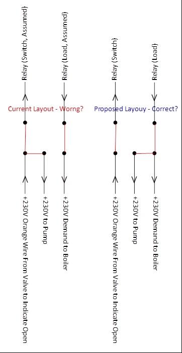
I was examining the setup because I was looking to replace the thermostats with internet thermostats, and noticed that I think the UFH zone has been wired up incorrectly. The thermostats is connected to the valve, and then functionally, the wiring is as shown in the picture (I assume the standalone relay must be wired the way round I show, or the boiler would never switch on).
This current layout has to be wrong, or there is no point in the standalone relay. The (underfloor heating circulation) pump should be on the load side of the relay, not the switching side fed through the valve from the thermostat, or there is no point I can see in the relay.
What is the correct way of wiring it?
I can see two possible ways of wiring it the proposed way on the picture which would seem to be the best, since if the relay fails it wont switch the boiler on with no UFH pump. [The alternative way would be to wire the boiler demand and the orange wire from the valve together. Both layouts will cause something odd if the UFH pump were to fail, but this latter method will also cause something odd to happen if the relay fails.]
[Last year I had the 2 port valve controlling the UFH zone replaced after it got bucket of water over it... Assuming the above, if the guy who changed the valve only put the valve wires back in the wrong place, that would mean the system was incorrectly wired in the first place by the installer, since the pump is not controlled by the relay.]
[Edit: Thermostat is a Salus RXRT505 Receiver with a wireless stat http://www.salus-tech.com/products/...wireless-programmable-room-thermostat-868mhz/ ]
Wiring Diagram
The two zones are controlled by two separate thermostats.
I was examining the setup because I was looking to replace the thermostats with internet thermostats, and noticed that I think the UFH zone has been wired up incorrectly. The thermostats is connected to the valve, and then functionally, the wiring is as shown in the picture (I assume the standalone relay must be wired the way round I show, or the boiler would never switch on).
This current layout has to be wrong, or there is no point in the standalone relay. The (underfloor heating circulation) pump should be on the load side of the relay, not the switching side fed through the valve from the thermostat, or there is no point I can see in the relay.
What is the correct way of wiring it?
I can see two possible ways of wiring it the proposed way on the picture which would seem to be the best, since if the relay fails it wont switch the boiler on with no UFH pump. [The alternative way would be to wire the boiler demand and the orange wire from the valve together. Both layouts will cause something odd if the UFH pump were to fail, but this latter method will also cause something odd to happen if the relay fails.]
[Last year I had the 2 port valve controlling the UFH zone replaced after it got bucket of water over it... Assuming the above, if the guy who changed the valve only put the valve wires back in the wrong place, that would mean the system was incorrectly wired in the first place by the installer, since the pump is not controlled by the relay.]
[Edit: Thermostat is a Salus RXRT505 Receiver with a wireless stat http://www.salus-tech.com/products/...wireless-programmable-room-thermostat-868mhz/ ]
Wiring Diagram