Will send beer Thorn apollo to hive help please

So it’s a three way valve and this is the diagram for the wiring it goes to
 

Attachments

  • 3428C0BB-626D-48D7-AE09-4C763DC56649.jpeg
    3428C0BB-626D-48D7-AE09-4C763DC56649.jpeg
    215.5 KB · Views: 82
  • A7F46357-A9F8-42C2-B923-86EE1A8D75B2.jpeg
    A7F46357-A9F8-42C2-B923-86EE1A8D75B2.jpeg
    217.4 KB · Views: 78
Sponsored Links
Is the valve very old?
Valve make and model no?
Can you post a pic of the junction box with the cover removed?

For info: the Hive will not be connected directly to the boiler as it has to control the motorized valve, which then controls then boiler. There should be a wire from the ON terminal in the boiler to the junction box.

PS Just read your last post!
The valve is probably a year old or so,

Fist is the junction box
Second is the valve
Third is the wiring to the hive from the boiler all looks a bit of a mess
 

Attachments

  • ACB93C35-FCFC-41B0-BD44-017A583DCEAA.jpeg
    ACB93C35-FCFC-41B0-BD44-017A583DCEAA.jpeg
    274.6 KB · Views: 94
  • 99A1A287-DB8B-4DFF-880D-EA50858D21F1.jpeg
    99A1A287-DB8B-4DFF-880D-EA50858D21F1.jpeg
    159.9 KB · Views: 87
  • E2A171CB-E3F8-4051-813D-05C2D979189A.jpeg
    E2A171CB-E3F8-4051-813D-05C2D979189A.jpeg
    216.5 KB · Views: 87
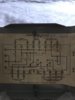
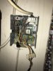
The junction box was not intended to be used with the Tower mid-position valve. It needs to be replace by a standard 10 position wiring centre. Here is the basic wiring diagram, which needs modifying as follows:

full


1. Ignore the room stat (it's built into the Hive)
2. Link 4 to 5
3. The Hive replaces the Time controller and wired as follows:
L to 1
N to 2
1 to 7
2 not used
3 to 6
4 to 4
The boiler has pump overrun, so you need to follow the diagram on the left.

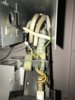
The Hive relay box will need to be near the pump and valve, probably upstairs.
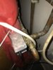
There will be five wires between the junction box and the boiler: Live (1), Neutral (2), Earth (3), Pumped Live (9) and Switched Live (10).

The Pumped live wire connects to PL terminal in the boiler.
The switched live wire connects to ON terminal in the boiler.
Make sure that there is no link between HW and ON in the boiler.
The boiler timer needs to be disconnected, but left in place.
The off/timed/continuous switch is redundant
The CH/CH+HW switch is redundant
The Hi/Lo switch will still work
Neutral and Earth for the pump should be connected locally (terminals 2 &3 of junction box); there is no need to connect directly to the boiler.

It is important that there is only one source of electricity for the heating system. Do not take a supply for the boiler from a socket downstairs and use a separate source for upstairs, i.e the Hive relay box.
 
Sponsored Links
Do you live near Reading ? Do you wanna come and do it for me ? Looks a bit complicated for me I’ll pay you
 

DIYnot Local

Staff member

If you need to find a tradesperson to get your job done, please try our local search below, or if you are doing it yourself you can find suppliers local to you.

Select the supplier or trade you require, enter your location to begin your search.


Are you a trade or supplier? You can create your listing free at DIYnot Local

 
Back
Top