Wiring a fused spur dimmer switch

Joined
13 Feb 2024
Messages
4
Reaction score
0
Country
United Kingdom
I've searched on this forum a few times and there are similar topics but I can't seem to find something for this particular issue.

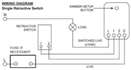
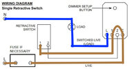
I'm replacing a normal fused spur light switch with a fused spur toggle dimmer switch. The dimmer unit is separate to the switch and the fuse and I'm struggling to work out how to wire it which I hope someone can help me with. I'm a beginner to wiring/electrics and I think what I'm missing is jumping from the dimmer unit to the switch?

Thank you in advance.

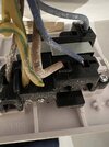
I've included pictures of the back of each of the modules/units - The dimmer unit is an Enkin unit as below, the back of the toggle switch, and the fuse unit itself is below.

1707827678798.png
Screenshot 2024-02-13 at 12.37.39.png
1707828067867.png
 
Sponsored Links
Years ago in the days of tungsten lights, there were supposed to be fuses built into the bulb, so if when they rupture there is ionisation the bulb fuse will rupture and stop the main fuse rupturing, and also protect any electronic switches.

However the bulb fuse was often missing, so a 1 amp fuse did give a little protection for the dimmer switch.

However when the fuse box had MCB's fitted they act in the main faster than a fuse, even 1 amp, and also faster than the fuse built into the bulb, a typical ceiling rose is rated 6 amp, so the 6 amp MCB/RCBO is in general terms good enough on its own to protect the lighting, as it is faster than a fuse anyway.

Where we have a larger overload, for example lights fed off socket supply we may still fit a fuse, but from bitter experance even a 1 amp the dimmer switch can fail first.

So question one is why is that fuse fitted? question two depends on one, is it still required?

I would assume a grid switch? To day in the main if I want to dim a light, I use a smart bulb, only with multiple lights would I consider a dimmer switch.

However I simply don't know why yours is wired that way, so can't really help.
 
Sponsored Links
Thank you everyone for your replies! Very much appreciated.

I've tried to mock up the diagram with the wiring as follows:

Is this right? Slightly confused as to where the earth wires go on this.
 

Attachments

  • wiring diagram .jpg
    wiring diagram .jpg
    109.8 KB · Views: 17
Years ago in the days of tungsten lights, there were supposed to be fuses built into the bulb, so if when they rupture there is ionisation the bulb fuse will rupture and stop the main fuse rupturing, and also protect any electronic switches.

However the bulb fuse was often missing, so a 1 amp fuse did give a little protection for the dimmer switch.

However when the fuse box had MCB's fitted they act in the main faster than a fuse, even 1 amp, and also faster than the fuse built into the bulb, a typical ceiling rose is rated 6 amp, so the 6 amp MCB/RCBO is in general terms good enough on its own to protect the lighting, as it is faster than a fuse anyway.

Where we have a larger overload, for example lights fed off socket supply we may still fit a fuse, but from bitter experance even a 1 amp the dimmer switch can fail first.

So question one is why is that fuse fitted? question two depends on one, is it still required?

I would assume a grid switch? To day in the main if I want to dim a light, I use a smart bulb, only with multiple lights would I consider a dimmer switch.

However I simply don't know why yours is wired that way, so can't really help.

It appears to be wired off a socket supply so I assume that is the reason why it's been originally wired with a fused spur switch.
 
Last edited:
I've tried to mock up the diagram with the wiring as follows:

Is this right?
I don't think so.

Why have you altered the diagram and connected COM to 1?
Are you not connecting 2 to 2? A switch with only one wire cannot do anything.

Surely it should be wired as in the diagram.

Slightly confused as to where the earth wires go on this.
All earth wires must be connected together at each accessory AND to the accessory if it is required and/or to the back box.
 
Yes you're right - So I would do Blue 2 to 2.

My confusion is that I will have 3 wires coming in from the Load, and 3 coming in from the Live, so 6 in total.

E.g. where would my neutral load, and where would my neutral supply enter the circuit?

It was previously wired like this as the original fuse spur switch if this is helpful?
 

Attachments

  • IMG_6012 2.jpeg
    IMG_6012 2.jpeg
    239.9 KB · Views: 10
Yes you're right - So I would do Blue 2 to 2.
Well, yes but it should be sleeved brown (or otherwise identified) to show it is a Line(live).

My confusion is that I will have 3 wires coming in from the Load, and 3 coming in from the Live, so 6 in total.

E.g. where would my neutral load, and where would my neutral supply enter the circuit?
It was previously wired like this as the original fuse spur switch if this is helpful?

1708098270242.png
 

DIYnot Local

Staff member

If you need to find a tradesperson to get your job done, please try our local search below, or if you are doing it yourself you can find suppliers local to you.

Select the supplier or trade you require, enter your location to begin your search.


Are you a trade or supplier? You can create your listing free at DIYnot Local

 
Sponsored Links
Back
Top