Wiring bath lift

Joined
27 Sep 2011
Messages
842
Reaction score
28
Country
United Kingdom
Fitting a bath lift and want to make sure my wiring is correct in advance

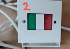
1. Wire cable from bath lift (1) directly to the isolator switch (2)

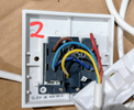
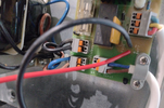
2. The other end of the isolator switch (2) is connected directly to (3) which contains a circuit board/ transformer/ batteries

3. Wire other end of (3) directly to back of socket i.e. ring main circuit or plug top

All of the cables are two core, no earth.


Battery Backup wiring

1. Connected +ve and -ve terminals from board (3) directly to the +ve and -ve terminal on each battery

2. Then took another cable and looped this between the two batteries +ve and -ve terminals
 

Attachments

  • IMG_20221217_131518853~2.png
    IMG_20221217_131518853~2.png
    1.4 MB · Views: 97
  • IMG_20221217_131625300~2.jpg
    IMG_20221217_131625300~2.jpg
    144.8 KB · Views: 111
  • IMG_20221217_131653091~2.png
    IMG_20221217_131653091~2.png
    1.4 MB · Views: 108
  • IMG_20221217_132959433.png
    IMG_20221217_132959433.png
    1.7 MB · Views: 116
  • IMG_20221217_133011746~4.png
    IMG_20221217_133011746~4.png
    1.3 MB · Views: 119
Sponsored Links
To start with it is a special location, so either scheme member or LABC will need to be involved.

Putting is simply it is not DIY work.

The bath panels with need a tool or key to remove them, and all not 12 volt behind panels which need a key or tool to remove. And of course will be inspected and tested by some one with the skills required, in the main the LABC shy away from this type of work, so it is not commercially viable for anyone not a scheme member, the fees are too high.
 
Sponsored Links
Not sure what's going on in your third picture (the back of the panel showing terminals). You have bare copper exposed in the red core, a nick in the yellow. A brown and blue conductors snipped of in the terminals an left.
 
Not sure what's going on in your third picture (the back of the panel showing terminals). You have bare copper exposed in the red core, a nick in the yellow. A brown and blue conductors snipped of in the terminals an left.
The item came like this. I would only work with fresh wire which hadn't been nicked/ copper exposed
 
To start with it is a special location, so either scheme member or LABC will need to be involved.

Putting is simply it is not DIY work.

The bath panels with need a tool or key to remove them, and all not 12 volt behind panels which need a key or tool to remove. And of course will be inspected and tested by some one with the skills required, in the main the LABC shy away from this type of work, so it is not commercially viable for anyone not a scheme member, the fees are too high.
It is a bath belt, which lifts the user.

You simply fit it to the wall and fit the the rod holder to the floor and that's it.

I would like to know whether the electrical installation will work. The item is used, and need to make sure that it works at the very least.
 
Supply must be RCD protected.
Connections myst not be inside a special location (bathroom).
Connection to “mains” must be through a fused double pole connection unit.
Is that 28v and mains in the one switch plate?
As above:
DIY job: NO
Notifiable work: YES
Scheme member required: YES
 
One thing we need to be careful with, is British regulations are not the same as the rest of Europe, so things designed for Europe can't always be used in UK without some mods.

1671360425178.png Where the 3 is one can see a transformer, this is clearly 230 volt, I have an old copy of the regulations which say
In zone l, only the following fixed and permanently connected current-using equipment shall be installed, provided it is suitable for installation in zone I according to the manufacturer's instructions:
(i) Whirlpool units
(ii) Electric showers
(iii) Shower pumps
(iv) Equipment protected by SELV or PELV at a nominal voltage not exceeding 25 V a.c. rms or 60 V ripple-free d.c., the safety source being installed outside zones 0, 1 and 2
(v) Ventilation equipment
(vi) Towel rails
(vii) Water heating appliances
(viii) Luminaires.
Note "safety source being installed outside zones 0, 1 and 2" and it does not list a lift, so the control panel must be outside the bathroom, or need a tool or key to gain assess, I know of people who have fallen foul of this as bath panels clipped in place, and did not need a key or tool.

I have tried to do work as DIY under LABC and it was not easy, the first hurdle is to get them to accept your signature on the installation certificate, unless they will, this means they will often appoint a third party to over see the work, so LABC charged £100 plus vat, and then the inspector will also charge around the same, so you pay around £250 to DIY so not worth doing as DIY cheaper to get a scheme member electrician.
 
Something not right with that switch, it looks like its 2 indicators either side and a switch in the middle. The switch then only has the affect of connecting the yellow to the red lamp, nothing back to the board. Surely the manual has detailed instructions for the wiring? though if they supplied cables stripped so badly then there's not much hope. You need to strip that cable back and get good undamaged cores to work with, and remove those cut off pieces of random wire.
 
Supply must be RCD protected.
Connections myst not be inside a special location (bathroom).
Connection to “mains” must be through a fused double pole connection unit.
Is that 28v and mains in the one switch plate?
As above:
DIY job: NO
Notifiable work: YES
Scheme member required: YES
-Supply is RCD Protected

-Nothing is in the bathroom, i simply want to test whether the equipment actually works before calling out a sparky and potentially wasting time/money

The sticker says 28V. But underneath, the actual plastic moulding says 250V
Connection to “mains” must be through a fused double pole connection unit.
I have a socket nearby

Do I need to replace this with a double pole connection unit? Then Wire other end of (3) directly to back of double pole connection unit

Also was my plan in my original post completely wrong?
 
Last edited:
Something not right with that switch, it looks like its 2 indicators either side and a switch in the middle. The switch then only has the affect of connecting the yellow to the red lamp, nothing back to the board. Surely the manual has detailed instructions for the wiring? though if they supplied cables stripped so badly then there's not much hope. You need to strip that cable back and get good undamaged cores to work with, and remove those cut off pieces of random wire.
That's odd. As far as i know it is part of the original equipment supplied with the machine.
 

DIYnot Local

Staff member

If you need to find a tradesperson to get your job done, please try our local search below, or if you are doing it yourself you can find suppliers local to you.

Select the supplier or trade you require, enter your location to begin your search.


Are you a trade or supplier? You can create your listing free at DIYnot Local

 
Sponsored Links
Back
Top