Wiring in a 1 gang 2 way Wifi switch no neutral

Joined
26 Feb 2026
Messages
8
Reaction score
0
Country
United Kingdom
Hi,
My living room has two 1 gang switches on either side, which power the main ceiling light which is a 48w LED affair.
I'm looking to replace the switches with two 1 gang WiFi switches which work 2 way.
Current wiring is as follows:
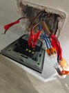
Master switch:
Comm: Single brown wire with constant 230V supply
'One Way' terminal: 3 wires, 2 brown, one black with brown sheath. I assume these would be switched live to light, a strapper and I'm not sure, another live going to another light? (the room only has one light)
'Two way' terminal: 2 wires. One brown and one sheathed brown black wire
3 neutrals terminated together in the 'loop' terminal

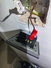
Second switch has 3 wires in total and no neutrals at all.

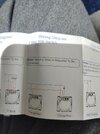
I purchased 2 of these:


Specifically the '1 gang, no neutral, 2 way' model.
Can anyone advise please? I've replaced several switches safely but when it comes to these no neutral Wifi switches I'm a bit confused
 
Do it as it tells you to..

Screenshot_20260226_214006_Chrome.jpg


Post pictures of your actual wiring if you're unsure
 
Each make can have their own method
1772181316732.png

The Energenie MIHO43 instructions here the TP-Link (Tapo) use a wireless button for second switch, which there is a version with a square cover surround, S200D has the cover S200B without cover
1772181663663.png
most battery operated devices need a hub, direct to a router uses too much power. The capacitor across the light increases the load to ensure enough current to work switch, and also stops the lights flashing when off.

The Energenie has minium wattage of 5 watts, and the Tapo uses a battery so no minium wattage, I am moving from Energenie to Tapo, as had some problems after some 5 years with them acting like a flasher unit, of the 5 fitted, now some 8 years latter down to 2, had a Tapo socket adaptor fail but as yet touch wood, no Tapo light switches have failed. At moment 4 fitted. Hub doubles as a door bell.
 
Last edited:
Two of the three switches it seems to have a neutral, but need as said to follow what the manufacturer says, each make is different, there is no one diagram fits all.
Sorry there are only 2 switches, I just took 2 photos of switch 1. Deleted one of them now for clarity
 
Permanent live
switch live
neutral

Screenshot_20260227_085936_Chrome.jpg


You should be able to re-purpose the 3 core to the 2nd switch?
 
If you do try it make sure you turn the power off obviously...

It looks like you need to fit the yellow adaptor at the light?

Also mark the wires so you can get it back how it is now incase you need to.
 
The yellow adaptor is a capacitor which will pass AC current, so it is basic a load on the switch even with bulbs removed, which is wasting energy if not required. I found with G9 bulbs I needed the load capacitor, with GU10 most would work without it, and E28 and BA22d never needed to fit one. But bulbs should be suitable for dimming which means they have the load resistor built in to stop flashing when off, the Tapo switch due to using a battery, does not need a neutral or any capacitors. And will work with any bulb type.
 
Not having any luck, cant get either to power on at all. Can anyone explain exactly where each wire is supposed to go?
 
I must have fried one of the switches because I put a confirmed 12v live to switch 2 and it doesnt illuminate anymore when connected to L. You have to put 2 wires in the L feed to switch one to provide a permanent live to switch 2, as switch 2 doesnt normally have its own permanent live. Got switch 1 working fine. Also the included wiring diagram is different to the one in this thread. Even though I ordered no neutral it says neutral is needed
 

Attachments

  • IMG_20260227_105646539.jpg
    IMG_20260227_105646539.jpg
    293.5 KB · Views: 5
  • IMG_20260227_105656074.jpg
    IMG_20260227_105656074.jpg
    393.2 KB · Views: 5
  • IMG_20260227_105717743.jpg
    IMG_20260227_105717743.jpg
    372.9 KB · Views: 5
EDIT: I hadn't seen your pics before posting this

I'm assuming wires 1 & 2 are the permanent line in and out and 3 (with the brown sleeve) is the switched line - and all 3 of those are the cables containing the blue neutrals
1772188600064.png

IF my assumption about those 3 matching with the 3 blues is correct suggest initially wiring those 3 browns like this and making sure the 3 blues are still connected together (in the N terminal if there is one)

1772190031169.png

And ensure one new switch works.

For now make sure wires 4,5 & 6 are safely protected (leave them in the ols switch?)

After it works we'll suggest the next steps.
 
EDIT: I hadn't seen your pics before posting this

I'm assuming wires 1 & 2 are the permanent line in and out and 3 (with the brown sleeve) is the switched line - and all 3 of those are the cables containing the blue neutralsView attachment 408880
IF my assumption about those 3 matching with the 3 blues is correct suggest initially wiring those 3 browns like this and making sure the 3 blues are still connected together (in the N terminal if there is one)

View attachment 408886
And ensure one new switch works.

For now make sure wires 4,5 & 6 are safely protected (leave them in the ols switch?)

After it works we'll suggest the next steps.
I did as you said and it didn't power on. However I switched the sheathed brown cable (which on the old switch was in the 2 way terminal) with the other 'i way' brown, the switch now works. So the sheathed brown wire must be the wire coming from the light.
To confirm at the master switch:

L = both solid brown wires from old one way terminal
L1 = Sheathed brown, brown wire which was connected to old 2 way terminal
Comm = isolated
3 neutrals = isolated
Black with brown sheath and grey with brown sheath = both isolated

The light turns on and off with no flicker, but switch 2 is dead
 
Not really, you are altering the wiring, I look at this 1772188995339.png and I count wires into one terminal, and it seems we have supply in, supply to light, and supply to other switch. So three cables.

Supply to other switch is likely the cable with one wire going to com, and using a meter easy enough to work out which cable is supply in, so the remaining cable is supply to light.

But the blue wire count shows you also have supply to next lamp, so you need to do more testing. As you have two cables one to light you are working on and one to next lamp, and need to work out which is which.

@pete01 has already identified unswitched line and switched line, so on the unswitched black to two-way switch, one brown is in and other out to next switch, so some we can work out.

Com Brown = to Com on other two-way switch. I will call A
1 way Black = to 1 way on other two-way switch. I will call B
1 way brown = one is feed in one supplies next switch. To L new switch
2 way grey = to 2 way on other two-way switch. I will call C
2 way brown = to light to L1 on new switch.
all Loop blue to N on new switch.

So A, B, and C go to second switch, and go like for like between the two switches, note it needs two smart switches, both old switches are replaced, and you need to program the switches.

Only diffrence I can see is new diagram shows neutrals connected.
 

If you need to find a tradesperson to get your job done, please try our local search below, or if you are doing it yourself you can find suppliers local to you.

Select the supplier or trade you require, enter your location to begin your search.


Are you a trade or supplier? You can create your listing free at DIYnot Local

 
Back
Top