
You are using an out of date browser. It may not display this or other websites correctly.
You should upgrade or use an alternative browser.
You should upgrade or use an alternative browser.
Need a time delay circuit for my float switch and 12v pump?
- Thread starter AquaHydroChem
- Start date
- Joined
- 16 Jan 2009
- Messages
- 119
- Reaction score
- 0
- Country


- Joined
- 27 Jan 2008
- Messages
- 28,905
- Reaction score
- 3,537
- Location
- Llanfair Caereinion, Nr Welshpool
- Country
The NE555 timer will switch states at 1/3 and 2/3 of supply voltage so with a potential divider and through a resistor either taking the control voltage high or low it would give a controlled delay in the output.
But I am not too sure exactly what you are trying to do. And is it for fun in which case yes play with 555 or is it more important in which case use a liquid control relay which has this all built in.
But I am not too sure exactly what you are trying to do. And is it for fun in which case yes play with 555 or is it more important in which case use a liquid control relay which has this all built in.
- Joined
- 16 Jan 2009
- Messages
- 119
- Reaction score
- 0
- Country
why not put a lead weight on the float switch?
The idea being to "dampen it"
.
That Idear I tried on Monday
Made an extension of the float using PVC tubing but because the size of the mixer tank I could only put a 5’’ extension on it
Put a plug on the end of it filled it with water to give it a slight positive bouncy
It did make a slight difference in the on off time/distance in mixer tank but when you empty the drain valve the pump could just about keep up with the empting of the tank (which is normal) and you sill had that on off rapid cycle from the float switch bobbing on the water
I guess the 5’’ extension was not enough probably needs to be something like 18’’ but I don’t have that room in the mixer tank
On the other hand there are probably quite a few ways to do what you want, but as you know little about what you are doing and how it works, contols company to make one for you.
That’s why i come onto a forum to ask the question
Looks like an astable multivibrator circuit to me
(Means it will work like a car indicator relay - tick tock!)
Do you not fancy a go at the circuit I drew above? Bit easier than one including 555 timers!
but i only have one float switch now the other is knacked
- Joined
- 16 Jan 2009
- Messages
- 119
- Reaction score
- 0
- Country
Looks like an astable multivibrator circuit to me
(Means it will work like a car indicator relay - tick tock!)
Do you not fancy a go at the circuit I drew above? Bit easier than one including 555 timers!
Not sure about wiring on car though
But dose a car indicator work on making a circuit through the indicator stork and the light coming on for 1 sec and then 1 sec off and back round again
On my system if the switch showed no circuit the pump would be off as soon as the water drops the switch give a circuit and the pump would switch on; a second latter coz of the rising water the switch would switch back off again but I still need that time delay of 5 or 10 before it switches off
- Joined
- 16 Jan 2009
- Messages
- 119
- Reaction score
- 0
- Country
But I am not too sure exactly what you are trying to do. And is it for fun in which case yes play with 555 or is it more important in which case use a liquid control relay which has this all built in.[/quote]
Just want to get the job done as quickly as pos rely
What is a liquid controlled relay?
Can’t rely find anything about it on the net
Just want to get the job done as quickly as pos rely
What is a liquid controlled relay?
Can’t rely find anything about it on the net
Spark123";p="1137910 said:Do you not fancy a go at the circuit I drew above? Bit easier than one including 555 timers
That’s quite a cheep float switch
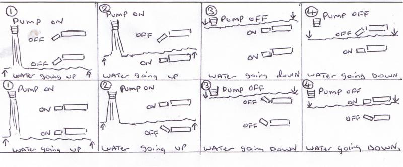
But I would need to check the sequence of the switches first
Now pay attention to the 2nd and 4th sequence
Notice how the switches are in the same order but one give a circuit to the pump and the other one is no circuit
Since I don’t rely have much with me at the moment apart from a 12 volt supply a few light bulbs and a flasher rely from a wagon
The machine is down in a barn in Tebay which is a 20min drive down the road for me
I could always use the lower mixer tank engine shut off float switch as a dummy run to see if it works first
This one?Wasn't that a proper commercial control system?
There was a properly printed schematic - where did that come from?
Surely unless you're carrying out some industrial process which hardly anybody else has ever done there must be an off-the-shelf system you can get which will turn a pump on and off in the manner you describe?
the original schematic I posted cane from the manual it self
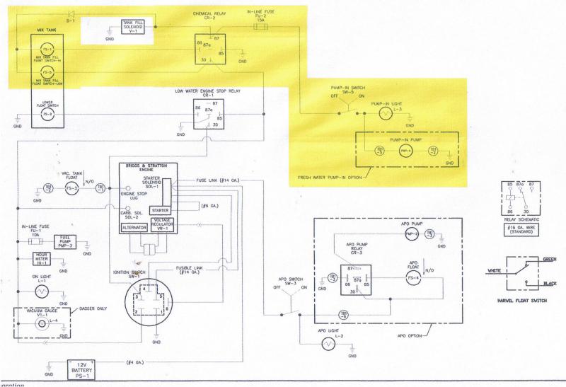
Came from the manual for what?
Well unless you know for sure that the pump will always need to start a fixed amount of time after the level starts to drop, or run for fixed amount of time after it gets to the low level then you're going to have to replace it.but i only have one float switch now the other is knacked
Whatever control circuitry you have if there is any variability in the timings for the pump starting and stopping you are going to have to have a sensor at high- and low-water marks....
I think you are thinking about it too deeply!Now pay attention to the 2nd and 4th sequence
Notice how the switches are in the same order but one give a circuit to the pump and the other one is no circuit
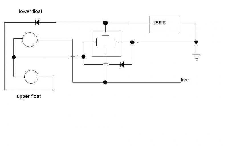
The switches I know of just operate on gravity i.e. when the float is horizontal the switch is on one state and when the float operates it changes state.
The diagram I drew above based on your original one works by the lower float operating as the water level drops (the top float will be in closed state also owing to gravity.)
This operates the relay and latches it via the diode. The pump then starts filling the tank. The water level will operate the lower switch but as the relay is latching the pump will continue to run.
Once the water level reaches the upper float switch and operates it the pump will switch off. The cycle will then start again, when the level drops past the upper float switch it will go closed again but the relay will not close until the lower one operates.
- Joined
- 27 Jan 2008
- Messages
- 28,905
- Reaction score
- 3,537
- Location
- Llanfair Caereinion, Nr Welshpool
- Country
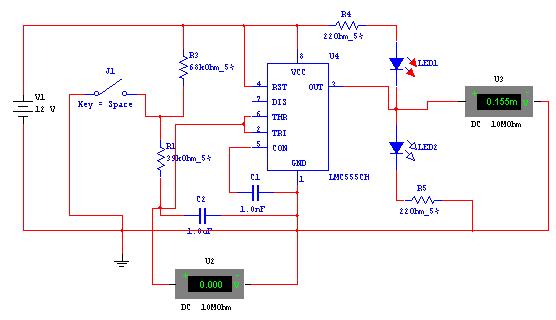
This circuit
is really an anti-bounce in that it has a min time in either mode so if your float switch was where my switch is shown then instead of reacting immediate there would be a delay which would stop the relay contacts from chattering.
This is theoretical as I don't know what times you want.
And yes it is a multi-vib circuit but instead of going to pin 7 it goes to float switch.
This is theoretical as I don't know what times you want.
And yes it is a multi-vib circuit but instead of going to pin 7 it goes to float switch.
- Joined
- 16 Jan 2009
- Messages
- 119
- Reaction score
- 0
- Country
spark123
I've re drawn your schematic Im worried about the load from the pump on to port 87 and there being a positive from live on to port 30 and then onto the float switches
Surly one of them is going to be overloaded
Just wondered why you drew your diagram so the switches wear the other way round
wear are you from
Err - using the KISS design principle, surely all you need is a single DP n/o contactor and a pair of float switches?
Can't be *rsed to post a drawing, but the lower switch energises the contactor, one set of contacts (A) is used to switch the pump.
The contactor is latched with a supply to its coil from the top float switch via the other set of contacts (B).
As the water level rises the lower float switch opens but the contactor stays closed because it's now got a supply independent of the lower switch.
As soon as the top switch opens that supply is shut off, the contactor opens and the pump stops.
As the level falls, even though the top float switch now closes, all that does is to reconnect the supply to the (B) contacts, but the contactor won't operate until the lower float switch closes....
DIYnot Local
Staff member
If you need to find a tradesperson to get your job done, please try our local search below, or if you are doing it yourself you can find suppliers local to you.
Select the supplier or trade you require, enter your location to begin your search.
Please select a service and enter a location to continue...
Are you a trade or supplier? You can create your listing free at DIYnot Local