What’s the point in buying more switches just to blow them up again for the sake of silly bugers and yes going round in circles with the same old plan just a couple of wires swapped round that’s all
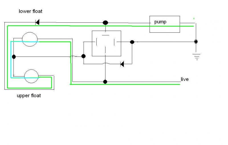
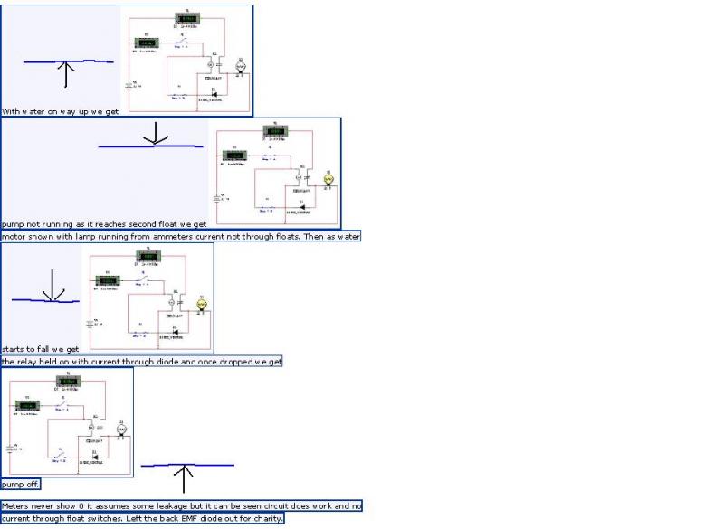
Then, as at least five people must have already said, use a control system with latching contact on the lower 'fill' switch, and have the upper 'full' switch break the latch. This WILL eliminate the bounce, and it's very simple, but you seem to have some compulsion not to replace the broken fault switch.
If you have something different to what I have tried then perhaps you could be so kind to show us a sketch and to stop all this insanity
ericmark";p="1139423 said:
I will agree that the liquid control units are designed for probes rather than floats but if one wants you can still use a float which I have done where there were suds on the water which was upsetting the probes.
But since his floats are US anyway why not use probes?
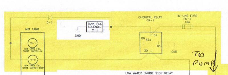
Seems to me he wants to fix it spending no money and without the knowledge required to manufacture any control circuits. The diagrams given by AquaHydroChem and Spark123 should have done the job.
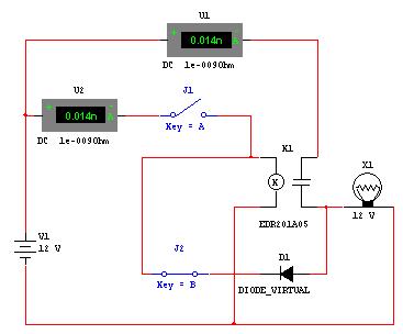
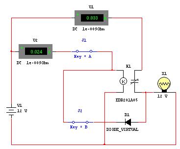
I am loathed to make up electronic boards for a one off job as someone in the future is going to really be scratching their head at how to fix. Although I gave the rough design for using a 555 timer at that time I thought it was a home project for fun no a commercial venture.
As already said the use of a PLC will do all he wants but most PLC's I have used are either 230vac or 24vdc so some device would be needed to boost voltage. And far more expensive than a new float.
What do you mean by probs and plc’s
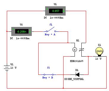
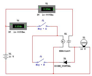
And the diagram has not worked and you can see why look!
I could even hear the switch burning out
Always wondered what that noise was in the past, thought it was the pump not getting enough power now I know it was the switches fizzling out
A set of stainless probes and ensuring they remain isolated from each other and the tank (if metal) are going to cost more than a float switch.
tank is plastic
[1] Spend a bit of money now and have peace of mind that future repairs will be just a change of a relay ( circa £3 ) and five minutes loss of use of the machine if you have kept a spare relay available. (24 hours if you have to buy one )
[2] Scrimp on the repair now and have a repeat or similar fault and head scratching some time in the future. Quite soon if the float switches cannot cope with the currents they have to switch.
so what are you saying buy latching relay or slave relays and wire it up as spark123 has shown
I totally agree. But if he is worried about water sloshing and wants to add timers to minimise this then he needs to spend money and fit a device not home made to do this. On the other hand if he does not require timers to stop this then you have already given him a good circuit diagram and there is no need to modify what you and AquaHydroChem have already done.
.
but its blown the switch so it dose not work
A set of stainless probes and ensuring they remain isolated from each other and the tank (if metal) are going to cost more than a float switch.
I totally agree. But if he is worried about water sloshing and wants to add timers to minimise this then he needs to spend money and fit a device not home made to do this. On the other hand if he does not require timers to stop this then you have already given him a good circuit diagram and there is no need to modify what you and AquaHydroChem have already done.
As to running on a single float then yes using a PLC he could use a float to change a mark / space relationship that runs to pump according to how often the float is activated. But far far simpler to just fit another float or probe.
And I have no intention of writing a PLC program as if he is too tight to buy another float he will not be fitting a PLC.
Until he returns I think we have given him all the advice he needs. I don't like the idea of using 555 timers as with these projects in the past I have found things like voltage ripple can completely mess up something that works A1 on a test bed. And unless designing for many units it is not worth the testing involved and minor mods for a one off project.
What is a plc?????????
_______________________________________
in the time I’ve been doing this and asking the question I am mind boggled to not of found an off the shelf system or mixer tank that dose all this


.gif)