Need a time delay circuit for my float switch and 12v pump?

Sorry I made a mistake on some versions the two contacts are not linked but it seems with bosch they are sorry.
But there are other relays available like here like this
n10_12aw_n33_35aw_mod_37514.jpg
maybe not longer made was a long time ago I did auto work. There were some relays used on ford which had different pin config but can't find any now.
 
Sponsored Links
I think the one he was using originally was a 25 or 30A relay - standard in a car.
 
Well I could not see anything wrong with original diagram. Two thoughts spring to mind.
1) Diode had gone short circuit.
2) Been replaced with wrong relay. I think it was ford who used one corner of coil and other corner for contacts. The numbers remained the same but physical position changed and I have seen a few people caught out with it.

I did look on Durite site as they use to have all the different types listed in their catalogue but seems they still don't do an on line version.
 
If you really want to go the 555 route RS components do a PC card for the 555 timer with options for monostable delay operation. They also do delay relays. I built a circuit using a 555 to make the central heating pump run on after boiler shutdown. The sensor was a current transformer on the boiler feed with a small circuit to provide a negative pulse to trigger the 555. Your float switch can be arranged to provide the pulse and contact bounce will not affect it as the 555 cannot be retriggerd until the time period has expired. Unfortunately the program that I used for PC design only ran on MSDOS so cannot use it now. If I can find the circuit I will post it on here.
 
Sponsored Links
quote="Spark123";p="1140108"][
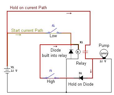
No, the current cannot flow in the direction you have indicated on the diagram as the diode prevents this.
If you missed the diode out of the wiring then yes, you could overload the switch. As I have said on a number of occasions now, you need to fit the diodes. As you look at a diode the white line corresponds with the line across the diode on the diagram.

Or as Ban-all-sheds is heading for, double poled devices will work too.[/quote]

Yes the diodes wear in place
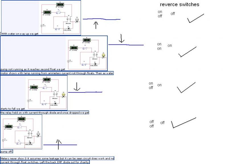
A diode is not there to reduce the current it is there to allow an electric current to pass in one direction and to block the current in the opposite direction

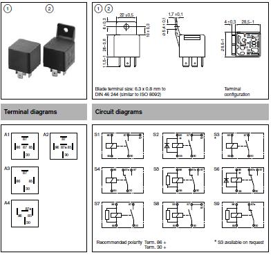
It’s a 4 pin standard 20/30 amp car relay as seen in the original schematic
And a 5 pin would not helf since 87a is just a common and not for reducing current

Well I could not see anything wrong with original diagram. Two thoughts spring to mind.
1) Diode had gone short circuit.
2) Been replaced with wrong relay. I think it was ford who used one corner of coil and other corner for contacts. The numbers remained the same but physical position changed and I have seen a few people caught out with it.

I did look on Durite site as they use to have all the different types listed in their catalogue but seems they still don't do an on line version.

Dose not matter which way the pins are placed on the relay just as long as you follow the diagram on the rely with relation to numbers
Other wise the sequence would not work
And the sequence of the original diagram worked perfectly when I used hard core standard switches

The easiest way of getting round this is to use 15 map rated float switches
And if anyone knows wear I can get them if it meant paying 30 quid for them then id have it
Coz I know it would do the job
Had a look at some tilt switches coz you could put that into a ball float and make a float switch
But again they wear only Mickey Mouse 300ml 1amp max
 
Ericman
I have looked at your diagram again and swapped the switches round in the diagram
The sequence now works
If you are so sure that the current wont blow the switches then I think I will make a circuit up on my desk
But before I do I need to know what some of the items are in the schematic
What are the U1 and the U2 with the green numbers inside?
What is the K in a circle?
Next to that I’m presuming it’s a capacitor can I pinch one from an old mother board

 
You may be able to get parts (or be told where to get them) if you contact

http://www.hydramaster.co.uk/

The Spitfire does not appear to be a current product in the UK but is shown on the USA site http://www.hydramaster.com/

But consider this. If the original switch failed then there may be a another fault in the system and if this fault is still there then the new switch is likely to be overloaded and it will fail.
 
U1 and U2 are not required only inserted to show no current through the floats.
K1 is coil of relay.
This is the same diagram as you already have. Do you know how to test a diode as I think that is all that is wrong.
Master diagram as I say same as what you have only re-draw so I could run it in simulator program. The diode across relay contacts is built into relay it is not in your circuit.
 
Can't believe people are still f@rting round with ideas of 555 based timers and diodes.

Or have I missed something? Apart from potential back EMF from the coil, is there a fundamental flaw with my KISS design? Is it actually a MITSS?
 
I don't think it will work with a capacitor in there, all it will do is charge up and block the DC current from flowing.
I still don't see what was wrong with the nice and simple diagram I drew before, 2 diodes, 1 car type relay and a couple of float switches. Or use 2 relays, one as a pilot relay to control the other which is then used to control the heavy load.
Or you could see if you can find a DPST/DPDT relay which can handle the current of the motor.
 
Yep, a double pole single throw relay will do, a double pole double throw will also do the job - just means some of the contacts aren't used. Octal relays which have 2 or 3 sets of contacts would do (which is what we tend to use for control purposes) providing they can be found in the correct current ratings.
 
Automotive relays capable of switching 10's of amps are easy to find - I used to have a box full of them under my bonnet for all the lights.

Never looked for a DP one though...
 
I can't remember seeing any which are DP either, might be easier to connect 2 x SPST coils together and use one for the control and the other for the power.
iirc the octal ones are usually rated about 10A but can't remember if that is AC or DC or both!
 
I can't remember seeing any which are DP either, might be easier to connect 2 x SPST coils together and use one for the control and the other for the power.
I was thinking that too.


iirc the octal ones are usually rated about 10A but can't remember if that is AC or DC or both!
Do you get octal base ones for automotive applications? I'd have thought vibration would be an issue...
 

DIYnot Local

Staff member

If you need to find a tradesperson to get your job done, please try our local search below, or if you are doing it yourself you can find suppliers local to you.

Select the supplier or trade you require, enter your location to begin your search.


Are you a trade or supplier? You can create your listing free at DIYnot Local

 
Sponsored Links
Back
Top