

If you're self employed, unless you're paying someone to do the design for you, yes you should be doing the design as well as the installation.I suppose the point is design and installation are separate and although as an electrician we are trained to install should we also be doing the design?
Test results should only be verification of the design calculations so without a design you can't really install.
I agree that for the average domestic installation you can base the design on previous installations and experience. But throw in a shed or workshop at the end of a garden and out comes the calculator.
Because for various reasons we often cannot fully live test our installations we have to attach our design calculations to the EIC to show compliance. The NIC have never had a problem with this, in fact they are more than happy to see the design. But I had to invest in software otherwise the designs would take far too long. (for me anyway)
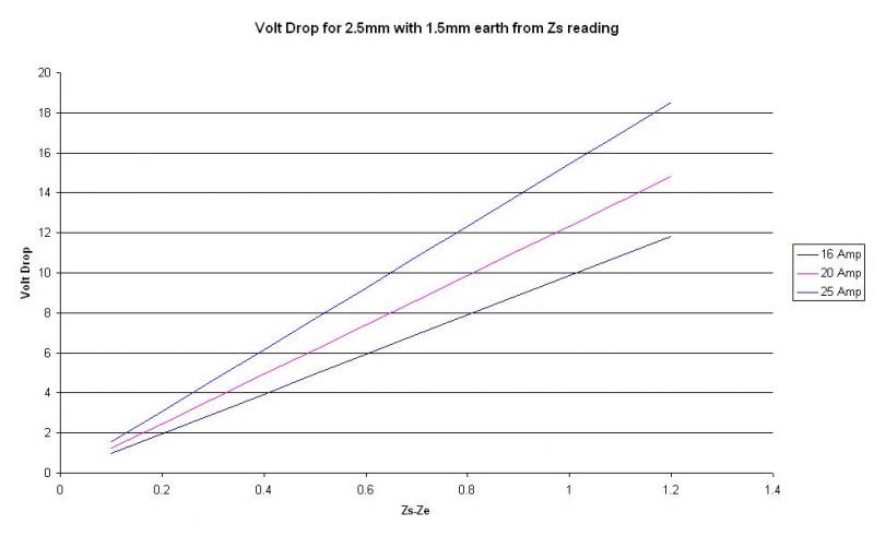
 voltage. So for lighting, 3% of 230v = 6.9v, therefore if you measure a vd of 7v on a (actual) 240v circuit thats a failure eventhough 3% of 240 = 7.2v.
 I didn't read the opening sentence properly