

Hi,
I'm having problems understanding the exact configuration of the CH/HW piping in my house.
In particular, I have to understand where and how to place piping for additional radiators at the upper floor.
My configuration is the classical one: loft cistern, indirect cylinder on the upper floor, gas boiler on the ground floor. (my house is a two-floor terraced house, quite standard I'd say)
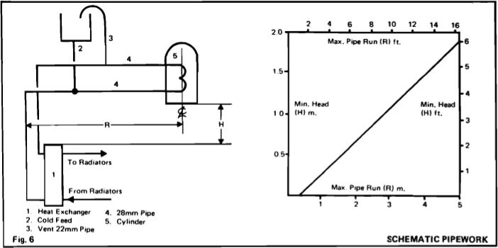
This is the official installation diagram taken from the boiler's installation guide (I think "heat exchanger" can be identified with "boiler" for our purposes):
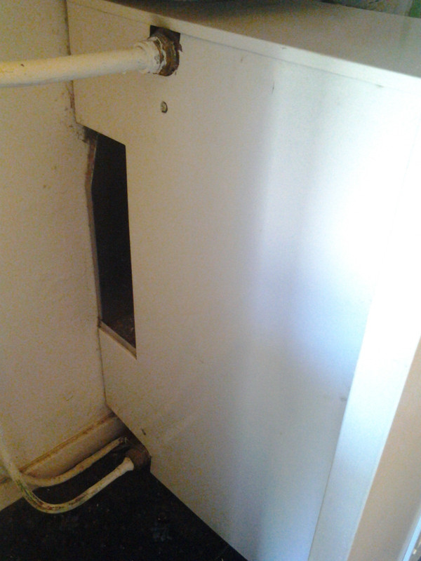
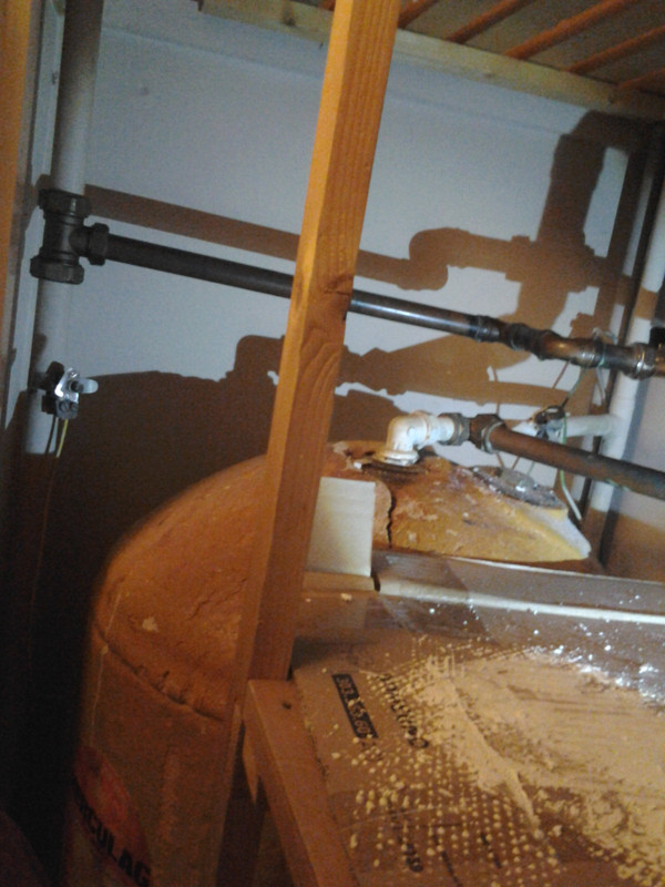
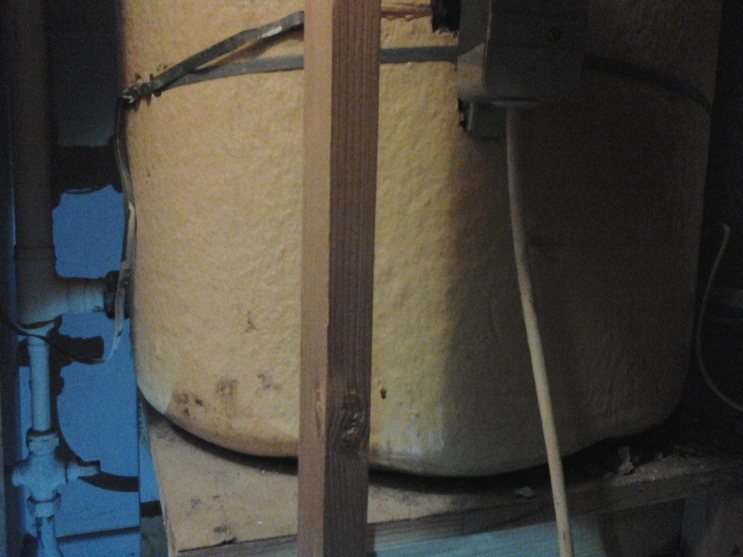
Contrasting that, this is how the boiler plumbing actually looks, from the left side (the smaller pipe on the bottom is irrelevant since it just passes through the boiler):
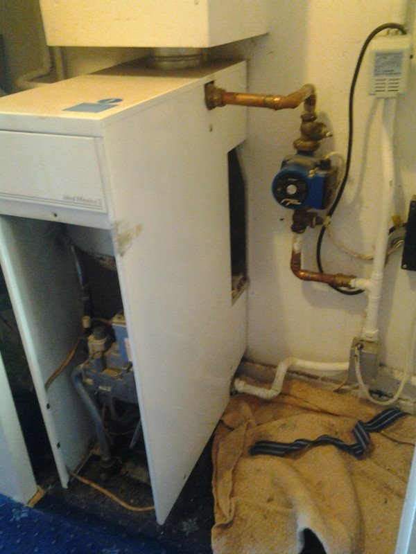
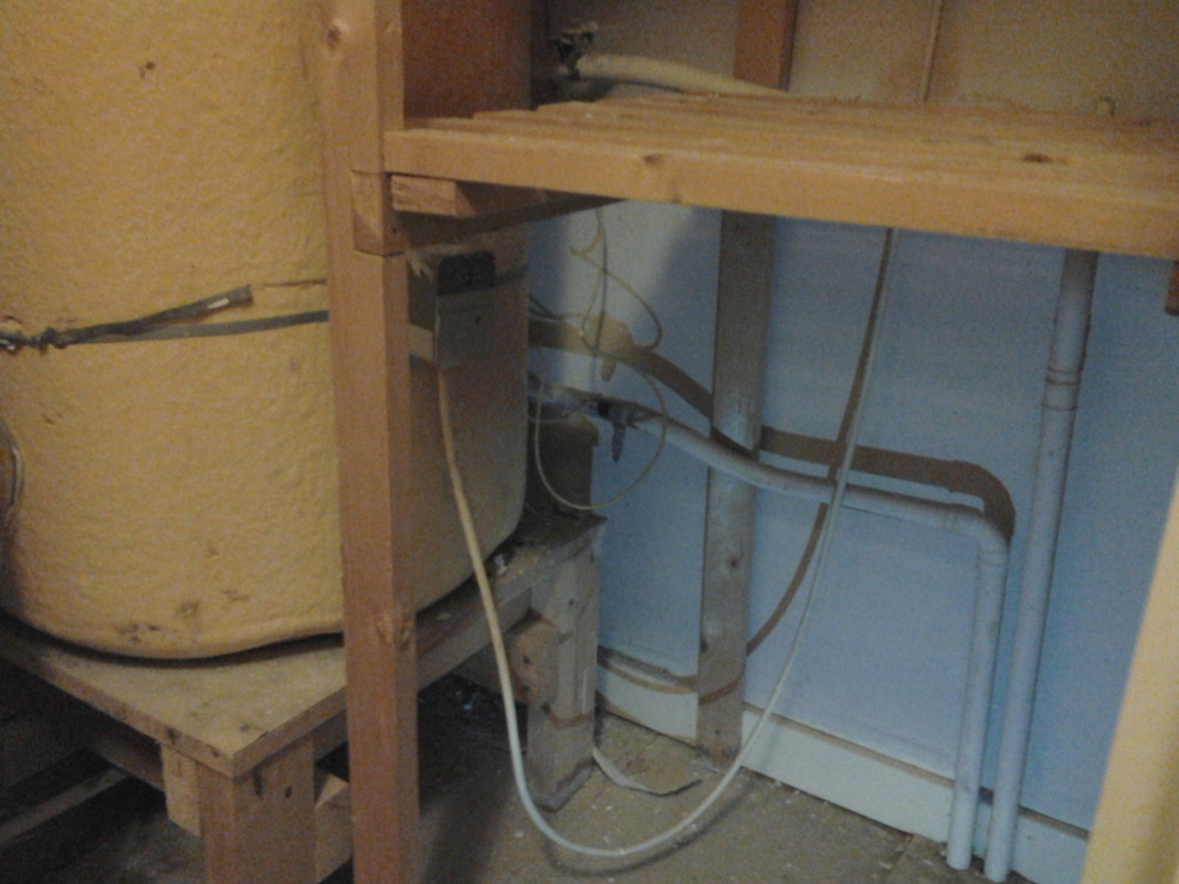
and from the right-hand side:
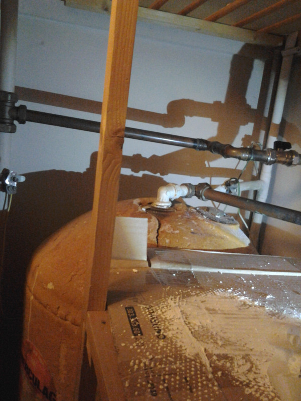
Given the number of pipes (4) attached to the boiler, and given the first figure, it looks like a non fully-pumped system.
However, the location and number of valves: one for HW (top right last picture) and one for CH (bottom right of last picture) suggests a fully-pumped one.
Any clue of what the actual situation is? Any test I could take myself to ascertain that?
And what about the radiators configuration? Is there a way to know if it's a two-pipe or one-pipe system?
As I mentioned, my main reason to know that is the perspective addition of radiators to the existing CH.
Thanks!
I'm having problems understanding the exact configuration of the CH/HW piping in my house.
In particular, I have to understand where and how to place piping for additional radiators at the upper floor.
My configuration is the classical one: loft cistern, indirect cylinder on the upper floor, gas boiler on the ground floor. (my house is a two-floor terraced house, quite standard I'd say)
This is the official installation diagram taken from the boiler's installation guide (I think "heat exchanger" can be identified with "boiler" for our purposes):
Contrasting that, this is how the boiler plumbing actually looks, from the left side (the smaller pipe on the bottom is irrelevant since it just passes through the boiler):
and from the right-hand side:
Given the number of pipes (4) attached to the boiler, and given the first figure, it looks like a non fully-pumped system.
However, the location and number of valves: one for HW (top right last picture) and one for CH (bottom right of last picture) suggests a fully-pumped one.
Any clue of what the actual situation is? Any test I could take myself to ascertain that?
And what about the radiators configuration? Is there a way to know if it's a two-pipe or one-pipe system?
As I mentioned, my main reason to know that is the perspective addition of radiators to the existing CH.
Thanks!
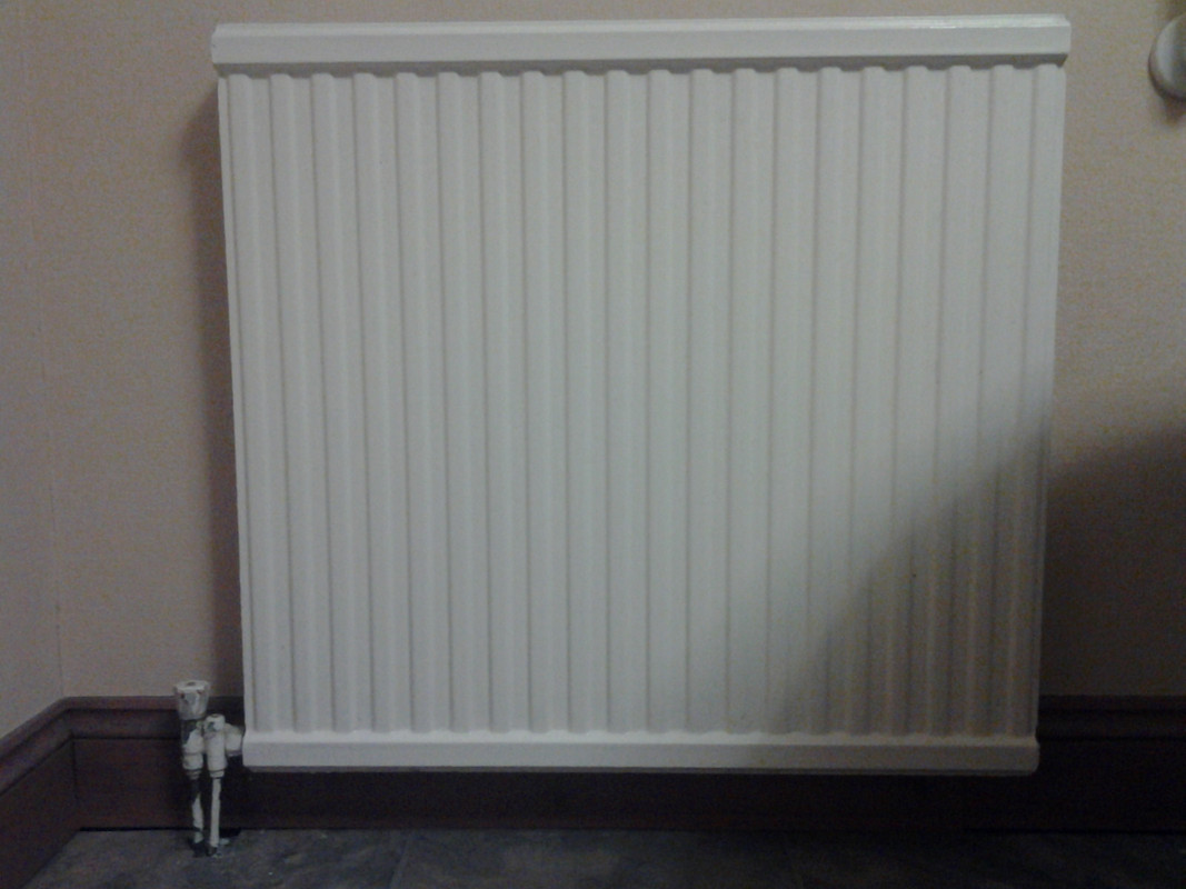
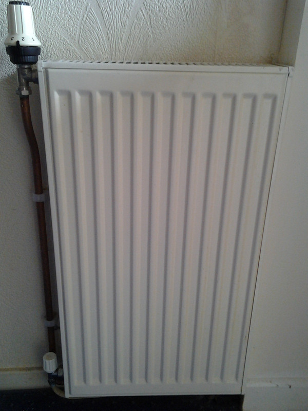

") : what are the names of the radiator valves in the last picture? Is the one on the right a TRV? What's the name of the other one?
: what are the names of the radiator valves in the last picture? Is the one on the right a TRV? What's the name of the other one?