I have an existing simply DPST switch that operates the heating, firing up the oil boiler and also turning on the pumps to circulate the water in the rads.
I'm trying to swap it out for Boost-button timer switch.
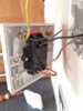
The existing switch, aside from earth, has L1 & N1 and L2 & N2 connections.
As you can see in the image, the L1 and N1 connections are both fed by the same brown wire, which is the only live wire. The L2 and N2 connections have grey and black wire attached.
My Boost button switch has L(IN) and L(OUT) and N(IN) and N(OUT) connectors. I'm not sure which to connect where.
The things I tried either don't work, or seem to work (the boost button starts up the boiler alright, but the circulation pumps run continuously).
Anyone able to clarify which to connect?
I'm trying to swap it out for Boost-button timer switch.
The existing switch, aside from earth, has L1 & N1 and L2 & N2 connections.
As you can see in the image, the L1 and N1 connections are both fed by the same brown wire, which is the only live wire. The L2 and N2 connections have grey and black wire attached.
My Boost button switch has L(IN) and L(OUT) and N(IN) and N(OUT) connectors. I'm not sure which to connect where.
The things I tried either don't work, or seem to work (the boost button starts up the boiler alright, but the circulation pumps run continuously).
Anyone able to clarify which to connect?
Attachments
Last edited: