Hi guys I wonder if you could help me I’ve fitted a hive thermostat to my boiler and it worked fine the boiler was turning on and off fine but the radiators didn’t get warm then in a cupboard I found what I assume are radiator valves they are wired as in the photograph I’ve attached,do these valves have to be removed now I’m using a different thermostat controller??? Thank you very much for your time

You are using an out of date browser. It may not display this or other websites correctly.
You should upgrade or use an alternative browser.
You should upgrade or use an alternative browser.
Fitting hive to my combi boiler
- Thread starter Scottjoby
- Start date
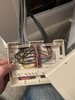
That looks like an S-Plan system with two motorised valves connected to it [black cables]. Do you have upstairs and downstairs zones?

In which case the Hive should be wired to the Zone valve, not directly to the boiler. The Hive needs to open the valve and then the valve starts the boiler.
If the valves don't open, the radiators won't get hot.
If you do have two heating valves you will need to Hives
In which case the Hive should be wired to the Zone valve, not directly to the boiler. The Hive needs to open the valve and then the valve starts the boiler.
If the valves don't open, the radiators won't get hot.
If you do have two heating valves you will need to Hives
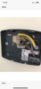
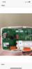
Good afternoon thank you for your help yes I have 2 thermostats at the moment. I bought 2 receivers and two controllers I looked at installing videos and it looked pretty simple. I’ve just moved into the property so found the two valves by chance in a void above the stairs. Would it be possible to find a wiring diagram as to where I need to fit which cables to which port as there are quite a lot in the existing block I’ve attached a photograph of the hive receiver block thanks again for your and trying to help me
Kind regards
Scott
Kind regards
Scott
Attachments
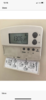
The wires that go to the existing thermostats need to be rerouted to the Hive Receivers. What make/model are the existing room thermostats?
Last edited:
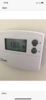
Hi there these are my existing controllers I have one in living one in the bedroom thank you
scott
scott
Attachments
-
 E3F28A26-D263-4AC9-B726-2AABE1C85641.png873 KB · Views: 280
 -
 12CA2EA0-9B26-419C-B7BD-EB7EFADBFD14.png846.4 KB · Views: 333
 -
 1D20D84B-2577-45CA-9895-23F510877383.png771 KB · Views: 311
 -
 B67D47A5-D4AB-4659-917D-356EDDC6F6C8.png872.8 KB · Views: 259
 -
 022E2484-A804-4B91-8D62-184211102CC4.png587.6 KB · Views: 281
 -
 32BFD066-59B1-4A3F-A3DE-58E1C29CCD7F.png940.2 KB · Views: 299
The wires from the existing thermostats go to the Hive terminals that are marked the same. So:
Wire in thermostat COM = Hive (1) Common
Wire in thermostat NO = Hive (3) Heating call for Heat NO
You can move the wires presently going to the existing thermostat to the Hive receivers; or disconnect the thermostat wires from the wiring centre and install new ones to the Hives directly. Perhaps locating the Hive receivers next to the wiring centre for convenience.
The existing Danfoss thermostats are battery powered so don’t have a mains supply, but the Hive receivers are mains powered so will need a 230V supply connecting to N & L. This should come from the same 3A fused spur that provides power to the rest of the heating system.
easiest way is to put the receivers next to the wiring center
- Joined
- 27 Jan 2008
- Messages
- 28,923
- Reaction score
- 3,540
- Location
- Llanfair Caereinion, Nr Welshpool
- Country

You do not say what boiler, so to improve the existing system it depends on what your willing to pay, and what boiler is fitted.
Hive works well with boilers with no option for ebus control, but you have two options if using Hive.
1) Fit two Hive single channel units.
2) Fit one Hive single channel unit and Hive TRV heads.
A electronic TRV head does the same job as a motorised valve, but instead of hard wired switches, uses a wireless link. You could leave the motorised valves in place, and just link them both together, easier than removing them, but you need a method to control which rooms are heated when, and the big problem is Hive TRV head costs around £54, so with 8 radiators in a house, that gets rather expensive.
There were 6 months ago cheap eQ-3 and Terrier i30 TRV heads which could be used in some of the rooms, to reduce the total cost, but with Brexit they seem to have dried up. They were some adds at under £10 each, but no more it seems.
If the boiler is OpenTherm enabled then EPH do thermostats that work as master/slave with your existing system.
There are two ways to control a modern boiler, one with ebus, the other with return water, with the latter there is a problem that a standard TRV can't turn boiler off/on it can only adjust output, Hive is designed to bridge that problem, so the TRV head sends a "demand for heat" to the wall thermostat, which then allows Hive to turn the boiler off when not required, but more to point on when it is required, and although the Hive wall thermostat does measure room temperature, it is really a hub which connects all rooms to one control using the signals from the TRV heads.
In real terms there are always rooms colder than others, so in some cases just 2 Hive TRV heads are enough, the rest can be stand alone, in my house I have 9 stand alone programmable TRV heads, and no linked head, and my problem is hall cooling time, it is too slow, so I have to set a schedule on the wall thermostat to ensure boiler runs when the TRV's calls for heat. The temperature on the wall thermostat changes 7 times a day, and when I am at home it works well. However when we leave the house and the geofencing turns off the heating, then it over shoots on return.
OK the problem is reduced in one way with a gas boiler in that is modulates, (I now have oil) but is also complicates things as well, as every time it switches off/on it takes time to adjust the modulation, so off/on switching must be reduced to minimum if your going to save fuel.
Two systems on/off and modulating can both keep the rooms in the house at the required temperature, but in the main, modulating systems do it cheaper fuel wise.
So start with boiler type and aims. But saving money is hard, if your gas bill is £300 and by all the cleaver systems you can reduce it to £250, then over 10 years you can gain if the bill for upgrade is under £400, I am allowing for interest paid on money, more than 10 years and interest also increases, so really have to base on 10 years, at £54 each for TRV heads plus the wall thermostat, it is hard to justify the expense.
I would turn off the heating when I left home, and back on at return, but then the boiler was running flat out without gaining the latent heat, but leave it on, and boiler would modulate so was gaining latent heat, so there is a balance, and under a set time away from house not worth turning the heating off.
But is seems no one has worked out what this time is. So with my oil boiler that does not modulate no question, saves money if turned off when I leave house, but not so cut and dried with a modulating boiler.
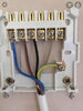
Would it be possible to find a wiring diagram as to where I need to fit which cables to which port as there are quite a lot in the existing block
There you go.
I assume that you mean these.

They are the live supply to the motorised valve microswitches. They need to remain in place. The micro switches are connected to the grey and orange wires. When the valve opens the microswitches operate and start the boiler. Don't confuse them with the grey wires from the room thermostats that weren't connected.

UP MV = the wires in the black sheath that go to the UP motorised valve. They don't change leave them as they are.
DOWN MV = the wires in the black sheath that go to the DOWN motorised valve. They don't change leave them as they are.
So in summary the wires in the right hand side of the terminals don't change.
The cables marked UP and Down on the left hand side are removed. They go to the existing room thermostats.
Perhaps if I redraw the diagram slightly it will clarify. Electrically it hasn't changed but the wires are located on the side of the terminals they are physically connected to.

They are the live supply to the motorised valve microswitches. They need to remain in place. The micro switches are connected to the grey and orange wires. When the valve opens the microswitches operate and start the boiler. Don't confuse them with the grey wires from the room thermostats that weren't connected.
UP MV = the wires in the black sheath that go to the UP motorised valve. They don't change leave them as they are.
DOWN MV = the wires in the black sheath that go to the DOWN motorised valve. They don't change leave them as they are.
So in summary the wires in the right hand side of the terminals don't change.
The cables marked UP and Down on the left hand side are removed. They go to the existing room thermostats.
Perhaps if I redraw the diagram slightly it will clarify. Electrically it hasn't changed but the wires are located on the side of the terminals they are physically connected to.
Last edited:
DIYnot Local
Staff member
If you need to find a tradesperson to get your job done, please try our local search below, or if you are doing it yourself you can find suppliers local to you.
Select the supplier or trade you require, enter your location to begin your search.
Please select a service and enter a location to continue...
Are you a trade or supplier? You can create your listing free at DIYnot Local
Similar threads
- Replies
- 4
- Views
- 648
- Replies
- 20
- Views
- 4K
- Replies
- 5
- Views
- 2K
- Replies
- 7
- Views
- 3K
D
- Replies
- 11
- Views
- 8K