Hi all. I am having a new consumer unit fitted very soon as I am on a really old fuse box which has been extended over the years (previous house owners) and it looks like something from North Korea. The new consumer unit is being done by a real sparky by the way.
The house is currently all on one ring main, with dedicated circuits each for shower and cooker. When the new unit is put it, I will be having the kitchen on its own circuit.
In prep for this I need to run new 2.5mm cable for the kitchen and put in a new cooker isolation switch in the kitchen as the current one is too far away and under the stair cupboard!
So, I have two parts to this for the prep as follows...
To save disruption and ring main traces cut out and re-splice the main ring main (this all needs to be done in one day ideally), I will be prepping by taking off the sockets in the kitchen and "passing the existing ring main cables through" and then connecting the sockets back to the new 2.5mm for the dedicated kitchen circuit. I was originally going to use connector blocks but then saw the following two products and felt they might be even more ideal, one for each Live / Neutral / Earth, stick them back in the backbox and put the socket back on. My question is, is this right and ok?
Wago 2-Way Lever Connector 221 Series 32A
https://www.screwfix.com/p/wago-2-w...00/8421r#product_additional_details_container
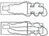
Ideal SpliceLine In-Line Wire Connectors
https://www.screwfix.com/p/ideal-sp...00/72727#product_additional_details_container
My 2nd part to this is the cooker, I have a new cooker ready to be connected to the new circuit. The existing cooker is a Kenwood range, max power 4.85.kW and is connected to a 30A fuse and an isolation switch (but which is too far away).
The new cooker is also a Kenwood range but newer model with power rating of 3.78kW. I am ripping out the old cooker circuit totally and running new cable to a new modern isolation switch close to the cooker. I was going to run the radial to the switch and then leave the cable coiled up where the new consumer unit will be but, upon a bit more reading on the Curry's website where we got the cooker it says, "this product requires hardwiring to a 17 amp fuse", then it also says "32 amp, requires hardwiring to a dedicated circuit". I get it that it needs it's own circuit and hence running this in but, what is the deal with the 17 amp hard wiring, where does that come in??
I want to get all this prepped ASAP so when I book the spark he can come in and pretty much rip out the North Korean style fuse board mess and connect up the new consumer unit. Any help on these 2 items is very much appreciated.
The house is currently all on one ring main, with dedicated circuits each for shower and cooker. When the new unit is put it, I will be having the kitchen on its own circuit.
In prep for this I need to run new 2.5mm cable for the kitchen and put in a new cooker isolation switch in the kitchen as the current one is too far away and under the stair cupboard!
So, I have two parts to this for the prep as follows...
To save disruption and ring main traces cut out and re-splice the main ring main (this all needs to be done in one day ideally), I will be prepping by taking off the sockets in the kitchen and "passing the existing ring main cables through" and then connecting the sockets back to the new 2.5mm for the dedicated kitchen circuit. I was originally going to use connector blocks but then saw the following two products and felt they might be even more ideal, one for each Live / Neutral / Earth, stick them back in the backbox and put the socket back on. My question is, is this right and ok?
Wago 2-Way Lever Connector 221 Series 32A
https://www.screwfix.com/p/wago-2-w...00/8421r#product_additional_details_container
Ideal SpliceLine In-Line Wire Connectors
https://www.screwfix.com/p/ideal-sp...00/72727#product_additional_details_container
My 2nd part to this is the cooker, I have a new cooker ready to be connected to the new circuit. The existing cooker is a Kenwood range, max power 4.85.kW and is connected to a 30A fuse and an isolation switch (but which is too far away).
The new cooker is also a Kenwood range but newer model with power rating of 3.78kW. I am ripping out the old cooker circuit totally and running new cable to a new modern isolation switch close to the cooker. I was going to run the radial to the switch and then leave the cable coiled up where the new consumer unit will be but, upon a bit more reading on the Curry's website where we got the cooker it says, "this product requires hardwiring to a 17 amp fuse", then it also says "32 amp, requires hardwiring to a dedicated circuit". I get it that it needs it's own circuit and hence running this in but, what is the deal with the 17 amp hard wiring, where does that come in??
I want to get all this prepped ASAP so when I book the spark he can come in and pretty much rip out the North Korean style fuse board mess and connect up the new consumer unit. Any help on these 2 items is very much appreciated.
")