
You are using an out of date browser. It may not display this or other websites correctly.
You should upgrade or use an alternative browser.
You should upgrade or use an alternative browser.
Bypass valve
- Thread starter toneloc
- Start date
- Joined
- 17 Feb 2019
- Messages
- 280
- Reaction score
- 19
- Country

Could be sludge partially blocking the boiler HEX and pump impeller or/and pipework, system may require a power/chemical wash,was the inhibitor level kept up in the system?.
It’s only 2 years old the entire system only went in in late 2023, inc boiler and all pipe work So I’d be surprised… unless it was installed very poorly… which ofcourse I couldn’t say for certain either way
System design could be an issue - if you have unusually long runs on the backbone and it's split to 2 opposite ends of the property. Central heating should be so designed whereby most of the flow is performed by the larger backbone, ideally in a circuit or to a central location and then the radiator feeds are kept to similar lengths. If there are extended runs to larger radiators in 15mm then that can cause major balancing issues.
Was the system properly flushed, inhibited and a mag filter added? How clean is the system water?
Was the system properly flushed, inhibited and a mag filter added? How clean is the system water?
- Joined
- 17 Feb 2019
- Messages
- 280
- Reaction score
- 19
- Country
System design could be an issue - if you have unusually long runs on the backbone and it's split to 2 opposite ends of the property. Central heating should be so designed whereby most of the flow is performed by the larger backbone, ideally in a circuit or to a central location and then the radiator feeds are kept to similar lengths. If there are extended runs to larger radiators in 15mm then that can cause major balancing issues.
Was the system properly flushed, inhibited and a mag filter added? How clean is the system water?
I've tried to draw the layout from memory so it wont be perfectly accurate, but probably very close to this.
Very thick lines - 28mm
thick lines - 22mm
thin lines 15mm
Black square around rad9-12 are the triple column ones.
I hav e wondered if the design of the layout could be a problem, but im not technical enough to know either way.
When it was installed im not sure if it was flushed actually. But it did have inhibitor in last time I bled it, and it does have a mag filter yes.
Well yep, that layout is a bit of a mare - could have been made a lot more intuitive by connecting each of those 22mm's together creating a single looped circuit. If the current runs could be coupled without too much of an issue then that would probably go a long way to evening out the system. At the moment each run has quite disparate loads and being extended like that would always cause a major balancing headache. How large are the other rads, not the columns, on average?
Balancing that setup would require a long time to get it right. Especially if you have those 4 large triple columns right in the middle of the 2nd circuit.
Balancing that setup would require a long time to get it right. Especially if you have those 4 large triple columns right in the middle of the 2nd circuit.
- Joined
- 17 Feb 2019
- Messages
- 280
- Reaction score
- 19
- Country
Should be
It should be relatively straight forward to connect them, it’s good access down the sub floor fortunately. I had a guy coming round in a couple weeks to take a look and see if he could find any obvious wrong doings, like a flow connected to a flow allowing short cycling etc. so I could always ask him to add a couple L / T fittings to hook those 22s up to a loop and chop the dead ends off to cut the loop a touch shorter
Excuse the phone “art”
Like this?

I suspected as much… to my untrained eye it looks as though that’s been setup to be zoned… but I never did ask for that so I did think it was potentially non optimal running two unconnected parallel runs like thatWell yep, that layout is a bit of a mare - could have been made a lot more intuitive by connecting each of those 22mm's together creating a single looped circuit. If the current runs could be coupled without too much of an issue then that would probably go a long way to evening out the system. At the moment each run has quite disparate loads and being extended like that would always cause a major balancing headache. How large are the other rads, not the columns, on average?
Balancing that setup would require a long time to get it right. Especially if you have those 4 large triple columns right in the middle of the 2nd circuit.
It should be relatively straight forward to connect them, it’s good access down the sub floor fortunately. I had a guy coming round in a couple weeks to take a look and see if he could find any obvious wrong doings, like a flow connected to a flow allowing short cycling etc. so I could always ask him to add a couple L / T fittings to hook those 22s up to a loop and chop the dead ends off to cut the loop a touch shorter
Excuse the phone “art”
Like this?
- Joined
- 17 Feb 2019
- Messages
- 280
- Reaction score
- 19
- Country
How large are the other rads, not the columns, on average
On id say average of 1.8m wide 60cm tall. Average 2.2k wattage per rad I’d say. Something like that
- Joined
- 17 Feb 2019
- Messages
- 280
- Reaction score
- 19
- Country
Found a solve for this eventually, incase anyone ever gets stuck with the same thing.
Had all the pipes inspected by a plumber, couldn't find a blockage anywhere or a wrongly connected pipe on the flow returns.
Had the boiler serviced and ruled out of any blockages.
Plumber suggested to me that perhaps the pump inside just wasn't strong enough, and suggested coming back in a couple weeks to fit an external pump to get the heat off the boiler quicker.,
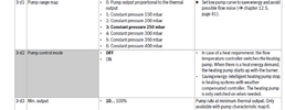
That evening from fiddling around with the settings one last time before giving up, i noticed that the pump output % was modulating down alot, sometimes even as low as 30% even when I had it set to run at constant pressure (option 6 of 3-d1) of 400mbar.
I noticed in the manual if the pump is set to option 0 (the option where the pump is relative to the burner). It allows you to set a min and max % range for the pump output. So as a test I set the pump to max 100% (default) and min 80% (10 is default). And this has made a world of difference.
:-Outlet pipe and rads got hot to the touch within 20mins, even the triple column ones which usually take much longer.
:-Boiler modulated down to 30% after everything got nice and hot, and stayed at 30% for the remainder of the demand.
:- Delta between flow and return stayed at 20 for about an hour, it did eventually close to 13 but the boiler continued to condens. So assume this is fine albeit not ideal.
So it would appear the pump was indeed the problem, essentially being too lazy. Now i just need to work out whether I leave it setup like this, or run an external pump instead.
Had all the pipes inspected by a plumber, couldn't find a blockage anywhere or a wrongly connected pipe on the flow returns.
Had the boiler serviced and ruled out of any blockages.
Plumber suggested to me that perhaps the pump inside just wasn't strong enough, and suggested coming back in a couple weeks to fit an external pump to get the heat off the boiler quicker.,
That evening from fiddling around with the settings one last time before giving up, i noticed that the pump output % was modulating down alot, sometimes even as low as 30% even when I had it set to run at constant pressure (option 6 of 3-d1) of 400mbar.
I noticed in the manual if the pump is set to option 0 (the option where the pump is relative to the burner). It allows you to set a min and max % range for the pump output. So as a test I set the pump to max 100% (default) and min 80% (10 is default). And this has made a world of difference.
:-Outlet pipe and rads got hot to the touch within 20mins, even the triple column ones which usually take much longer.
:-Boiler modulated down to 30% after everything got nice and hot, and stayed at 30% for the remainder of the demand.
:- Delta between flow and return stayed at 20 for about an hour, it did eventually close to 13 but the boiler continued to condens. So assume this is fine albeit not ideal.
So it would appear the pump was indeed the problem, essentially being too lazy. Now i just need to work out whether I leave it setup like this, or run an external pump instead.
A bit strange why the pump output was modulating at all on option 6 at a fixed constant pressure of 400mbar and also now at a far greater pump head and circ rate and rad output (if at the same flowtemp) that the boiler output is now only 30% vs ~ 40% previously.Found a solve for this eventually, incase anyone ever gets stuck with the same thing.
Had all the pipes inspected by a plumber, couldn't find a blockage anywhere or a wrongly connected pipe on the flow returns.
Had the boiler serviced and ruled out of any blockages.
Plumber suggested to me that perhaps the pump inside just wasn't strong enough, and suggested coming back in a couple weeks to fit an external pump to get the heat off the boiler quicker.,
That evening from fiddling around with the settings one last time before giving up, i noticed that the pump output % was modulating down alot, sometimes even as low as 30% even when I had it set to run at constant pressure (option 6 of 3-d1) of 400mbar.
I noticed in the manual if the pump is set to option 0 (the option where the pump is relative to the burner). It allows you to set a min and max % range for the pump output. So as a test I set the pump to max 100% (default) and min 80% (10 is default). And this has made a world of difference.
:-Outlet pipe and rads got hot to the touch within 20mins, even the triple column ones which usually take much longer.
:-Boiler modulated down to 30% after everything got nice and hot, and stayed at 30% for the remainder of the demand.
:- Delta between flow and return stayed at 20 for about an hour, it did eventually close to 13 but the boiler continued to condens. So assume this is fine albeit not ideal.
So it would appear the pump was indeed the problem, essentially being too lazy. Now i just need to work out whether I leave it setup like this, or run an external pump instead.
- Joined
- 17 Feb 2019
- Messages
- 280
- Reaction score
- 19
- Country
Yep… wondered exactly the same myself…. How can it be constant pressure if it’s modulating the output?A bit strange why the pump output was modulating at all on option 6 at a fixed constant pressure of 400mbar and also now at a far greater pump head and circ rate and rad output (if at the same flowtemp) that the boiler output is now only 30% vs ~ 40% previously.
And I wondered if that was actually a printing error on the manual… as that means at 100% on setting 0… it’s operating at 700mbar?
Is there an easy way to test the flow rate / flow speed the boiler is currently operating at?
Its quite easy to calculate the flowrate as long as you have accurate flow and return temps, you said you were buying more accurate sensors?
You know that the boiler % output is quite accurate so at say a steady 30% output, 36*30%, 10.8kW and if the flow/return dT is 15C, then the flowrate is, 10.8*860/60/15, 10.32LPM. flowrate in LPM = kW*860/60/dT.
If the pump head increased from 400mb to 700mB then the increase in flow should be the flowrate at 400mb x a factor of Sqroot of (700/400), 1.32.
- Joined
- 17 Feb 2019
- Messages
- 280
- Reaction score
- 19
- Country
Its quite easy to calculate the flowrate as long as you have accurate flow and return temps, you said you were buying more accurate sensors?
You know that the boiler % output is quite accurate so at say a steady 30% output, 36*30%, 10.8kW and if the flow/return dT is 15C, then the flowrate is, 10.8*860/60/15, 10.32LPM. flowrate in LPM = kW*860/60/dT.
If the pump head increased from 400mb to 700mB then the increase in flow should be the flowrate at 400mb x a factor of Sqroot of (700/400), 1.32.
In that equation.. where are you getting the 860 and 60 from? are they variables or static?
1Kwh = 860 kcal and there are 60 minutes in a hour. (860 = 3,600,000/4186)
Some use a very long winded formula but I've used this for over 60 years since my introduction to SI units.
So, kWh = LPM*60*dT/860 or any variation of this. ( I get mixed up in the lower/upper case of the units but the calc is fine), its actually kgs of water but a litre of water is generally taken a being 1 kg.
It can also be used say to calculate the energy required to heat a "tank" of water + time taken to achieve this with a heating element or coil, for example, energy required to heat a 200L cylinder of water from 10C to 60C = 200*(60-10)/860, 11.628 kWh.
(The long winded calc is, 200*4186*(60-10)/3,600.000.)
A 15kW heating coil or element will take,11.628/15, 0.775 hrs, 46.5 minutes.
DIYnot Local
Staff member
If you need to find a tradesperson to get your job done, please try our local search below, or if you are doing it yourself you can find suppliers local to you.
Select the supplier or trade you require, enter your location to begin your search.
Please select a service and enter a location to continue...
Are you a trade or supplier? You can create your listing free at DIYnot Local
Similar threads
- Replies
- 2
- Views
- 7K
- Replies
- 1
- Views
- 4K