Adding external light to electric garage door opener

Blooming heck that was quick, impressive and obviously extremely knowledgeable.
I didn't realise I could connect one side of the relay to the mains supply and the other side to the 12v output pins on the circuit board.'

That is the whole point of the relay.
It allows one voltage (in this case 12Vdc) to control a different voltage (in this case 240Vac).
And neither side sees the other side.

The relay acts as a simple switch, in this case stopping or allowing the 240Vac live to pass.

YOU MUST be careful with relays
It is easy to forget that there is 240Vac on some of the tracks (when you often only have 5 to 12V).
Test it first with the mains off and it unplugged.
The 12V will power it up and you will hear it switch (click) when lights should go on and off.

Also, If the light is 12V then I would have put the 240V to 12V converter (sometimes known as transformer) on the 240V wire after the relay, so transformers is only powered when relay is switched on.

SFK
 
Sponsored Links
Just to add.
My suggestion is buy ONLY the Molex cable and the relay module first.
Only these two items.

Then test to see if you can hear the relay click (or use mulitmenter to test relay).

This is safer for you (as no 240V) and a good way to test with minimal cost.

SFK
 
Just to add.
My suggestion is buy ONLY the Molex cable and the relay module first.
Only these two items.

Then test to see if you can hear the relay click (or use mulitmenter to test relay).

This is safer for you (as no 240V) and a good way to test with minimal cost.

SFK


Brilliant, thanks SFK, I'll do that and buy the two components first then report back, thanks again, truly appreciate it.(y)(y)(y)
 
Ok guys, got the molex connectors and yous were bang on, fit like a glove!

I've got the new relay /circuit board, on one side I have GND, IN and VCC, on the other I have CB, COM and CK. To test the relay by connecting it to the existing circuit board as advised what are the connections I should use?
 
Sponsored Links
Great to hear.

Connect the GRD+Gliderol to the Module with the MolexKK cable where:
- GND is for 0V
- VCC is for the permanent 12V (this powers the module all the time).
- IN is for the Switched 12V. (This is for the signal that controls the relay so teh relay switches on and off).

The module should now light up.
Best to now put the overrun timer to a very short (or zero) overrun time to aid testing.

You do not need any connection on the relay side to make the module work.

For reference the relay acts as a simple switch. Making a connection from COM to CK or to CB depending on the 12V signal to IN.
So later on you will:
-put the LIVE input voltage in at the relays COM. (In your case the 240V ac on the brown wire).
- and put the Switched live (240Vac brown cable) that then goes to the light into the CK or into the CB.

Do not do this yet, best to test without the 240V.

When the IN signal changes from 0V to 12V the relay switch moves from the CB to the CK. You should hear a click in the relay as its switch moves.

To test the module (and make sure I have the CK and the CB the correct way round) put your multimeter in COM and in CK.

Resistance should be infinite when motor not operating, and Resistance should go to near zero when door is opening.

If the reverse is true then move the wire from CK to CB.


Additional info from google search that suggests above is correct:
CB = Normally Closed (contacts are closed when not powered)
CK = Normally Open (contacts are open when not powered)

Sfk
 
Last edited:
Hi SFK, putting multimeter in CK and COM gives me the reading in the first photo (1.) And in CB and COM gives me the reading in the second photo (00.9).
 

Attachments

  • 20210225_175338.jpg
    20210225_175338.jpg
    395.7 KB · Views: 67
  • 20210225_175400.jpg
    20210225_175400.jpg
    285.1 KB · Views: 61
That is a good/correct result.

I am presuming the pictures are when the Door is NOT opening.

For reference, inside the relay imagine a wire permanently fixed at COM, and that can then move between CB and CK.
- When relay is not operated the wire touches and makes contact between COM and CB (voltage is able to go from COM to CB) .
- When relay is operated the wire moves off CK and touches and makes contact between COM and CB (voltage is able to go from COM to CB).

Looking at your Pictures:

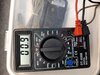
COM and CK - Multimeter shows '1' >>> This means infinite Resistance between COM and CK.
- No connection between COM and CK
- This means that this switch is OPEN between COM and CK,
- If you had Live (Brown) coming into COM and Switched Live (Brown) out from CK to your bulb, the bulb would NOT be lit.

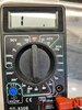
COM and CB - Multimeter shows '0.9ohms' >>> This means No (very little) Resistance between COM and CB.
- There is a connection between COM and CB
- This means that this switch is CLOSED,
- If you had Live (typically Brown wire) coming into COM and Switched Live (typically Brown wire with black sleeve) out from CB to your bulb, the bulb WILL be lit.


Again - I am presuming that above pictures is when the Door is NOT opening
- From now on ignore connection CB and do not use it (otherwise bulb will on all the time when motor not working and off only when motor working).
- Only use the two connections "COM" and "CK".
- This is now your switch that will later control your bulb.

Put your multimeter into COM and CK.
- Multimeter will show '1' for Infinite Resistance between COM and CK because there is no wire in the relay between these two contacts. (and so imagine your outside bulb not being lit).
- Open your garage door.
- If all works properly the Relay will be triggered moving the wire inside it so it is between COM and CK, and the multimeter will change to show a low resistance say '0.9ohms' between COM and CK meaning switch is now CLOSED (imagine your outside bulb now being lit).
- When motor stops working, the relay will be un-triggered removing the wire between COM and CK, and Multimeter will again show '1' for Infinite Resistance between COM and CK (the motor might have a inbuilt delay to keep light on).

SFK
 
Last edited:
Ummmm....I think I have to admit my stupidity, I just bench tested it, the circuit board wasn't connected to the door opener, what a muppet! I'll follow that process this weekend and report back, thanks again.
 
Ok, connected the relay module to my main circuit board and these are the multimeter readings, I'm very confused as there's no difference!


When door not operating:
CK and COM = 1
CB and COM = 0.9

When door operating:
CK and COM = 1
CB and COM = 0.9
 
I assume you cant hear the relay operating when the door is operated, there should be a noticeable click (and if in doubt, if you hold your finger on the top of the cae, you'd be able to feel the contacts pull in)
 
dstil,
Sorry to hear that.

First some questions and then a simple test.

1) Which relay module did you buy (can you post an ebay link?)?


2) When Relay Module is connected to the 0V (GND) and 12V (VCC) and Switched_12V (IN) of the motor does the relay module turn on and light up (ie are its LEDs on?).


Now for my quick test...

A) Get a short length of thin wire.
On the relay module screw the wire into the Switched 12V (IN) connection.
Leave the other end loose for now.

B) connect the Relay Module to 0V (GND) and 12V (VCC) of the Motor (or some other power source)
DO NOT connect the Switched_12V (IN) to the Motor.

If all is okay the Relay Module should turn on and light up as per question 2.

C) Take the loose end of the wire that is screwed into the Switched 12V (IN) connector.
Touch this loose end of the wire into the bare metal of the 12V (VCC) connector.
This is to temporarily put 12V into Switched 12V (IN) connection.

When you do this does the relay change the position of its internal switch?

D) When you remove the loose end of the wire from 12V (VCC) does the relay change the position of its internal switch back again,

SFK
 
It's fine, I appreciate its all trial and error and I'm not the perfect student!

Here's an image of the relay module I bought, I'll do the tests you mention and report back.

Thanks again.
 

Attachments

  • Screenshot_20210301-192347_eBay.jpg
    Screenshot_20210301-192347_eBay.jpg
    137 KB · Views: 61
Forgot to say, when i connected the relay module to the connector on my door motor the countdown timer was illuminated.
 

DIYnot Local

Staff member

If you need to find a tradesperson to get your job done, please try our local search below, or if you are doing it yourself you can find suppliers local to you.

Select the supplier or trade you require, enter your location to begin your search.


Are you a trade or supplier? You can create your listing free at DIYnot Local

 
Sponsored Links
Back
Top