3 device in parallel on one cable

Joined
5 Jan 2008
Messages
204
Reaction score
3
Location
Manchester
Country
United Kingdom
Hi all. Probably quite a simple question.

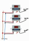
I have 3 temperature controllers with thermometers. I don't want to use the controllers, just the thermometer).

They are all 240v

I have mounted them to a board and want to have one 240v cable on a socket to run them in parallel.

Question 1: what is the best way to use the cable without cutting it to connect these up to?

Question 2: can you solder 240v devices onto a cable as opposed to using a connector of sorts.

Thanks
 

Attachments

  • Notes_221210_102947.jpg
    Notes_221210_102947.jpg
    324.9 KB · Views: 51
Sponsored Links
How far apart are these devices going to be?
Are they going to be semi/permanently mounted?

...just a quick look for xh-w3001 shows 12V versions or 220V AC - the 220V AC versions look particularly dodgy for use on our mains supply.
It is supplied with a red and black cable for connection to the supply, rather than a double insulated mains lead.
 
Last edited:
There is some special cable which you can connect to with special pins which go through the outer, last I used was 24 volt used with PLC's, seem to remember some problems using it with 230 volt, but in the main one wants some cable clamps, I would suggest a lighting junction box like this easy
1670669942738.png
to use and clamps the cable, the Hager Ashley J501.
 
Sponsored Links
Question 1: what is the best way to use the cable without cutting it to connect these up to?

Question 2: can you solder 240v devices onto a cable as opposed to using a connector of sorts.
1) Depends, how long is a piece of string?
Why do you not want to cut it? Get a long cable and wire from the first, round to the 2nd and so on like a daisy chain, connecting the live from the first along with the live out to the 2nd in the same terminal, then when you get to the third connect the live from the 2nd and the live from the length that goes to the plug into the 3rds live terminal.

Do this for the Neutral and Earth into their respective terminals too.

As long as no copper is dangling out of the terminal and both are firmly secured in it then they should be fine.


2) Why do you want to solder them? do they not have screw terminals?
 
How far apart are these devices going to be?
Are they going to be semi/permanently mounted?

...just a quick look for xh-w3001 shows 12V versions or 220V AC - the 220V AC versions look particularly dodgy for use on our mains supply.
It is supplied with a red and black cable for connection to the supply, rather than a double insulated mains lead.
The version we have is 240v.
They will be mounted on a board which is hung. So it can be removed and un plugged.

I did think it was odd that they have a red and black, also the instructions said red to live black to neutral, which is so odd.

I did forgot if I extend the probe cable, will it make a difference to the measurements?
 
Working in the controls industry we tried these devices, they had all sorts of hope and appeared to fufill many promises...

they disappeared rapidly from our list of worthwhile products, one of the problems was loss of thermistor resulted in the device staying in one state and the construction quality was horrendous, a fairly minor knock of the thermistor was often enough to make it fail.

Oh and the wires were frequently wrong colours or simply soldered to the wrong place on the board.
 
1) Depends, how long is a piece of string?
Why do you not want to cut it? Get a long cable and wire from the first, round to the 2nd and so on like a daisy chain, connecting the live from the first along with the live out to the 2nd in the same terminal, then when you get to the third connect the live from the 2nd and the live from the length that goes to the plug into the 3rds live terminal.

Do this for the Neutral and Earth into their respective terminals too.

As long as no copper is dangling out of the terminal and both are firmly secured in it then they should be fine.


2) Why do you want to solder them? do they not have screw terminals?
Rather than having chunky terminal blocks I thought if I strip 2 single core cables along the cable I can simply solder the red and black as required, no cuts.

The device has no screw connectors.
 
the 220V AC versions look particularly dodgy for use on our mains supply.

I would recommend using 24 Volt units and use a good quality 230 AC to 24 V DC power supply to provide power to the units.

I did forgot if I extend the probe cable, will it make a difference to the measurements?

Increasing the length of the lead to the sensor will add resistance to the sensor circuit and hence the accuracy of the readings will be affected. That said the effect of adding a few Ohms will be too small to be of any concern.
 
The version we have is 240v.
Fair enough :)
They will be mounted on a board which is hung. So it can be removed and un plugged
Because of the lack of double insulated cable connections, if I was to use these (especially as they are to be mounted together); I would fit them all into an enclosure (with cutouts for the display) - there would then be no problems with lack of DI, and you can make your connections inside with a standard terminal block.
One mains cable could enter through a cable gland.
 
Fair enough :)

Because of the lack of double insulated cable connections, if I was to use these (especially as they are to be mounted together); I would fit them all into an enclosure (with cutouts for the display) - there would then be no problems with lack of DI, and you can make your connections inside with a standard terminal block.
One mains cable could enter through a cable gland.
Or butt them up to an enclosure or a piece of trunking dedicated for the job.
 
Last edited:
So they're all fused/can be isolated

View attachment 288484
You're missing the step that would make this device suitable to be connected to a mains plug, in the first place! ;)

1670681688424.png


Having said that, and having a look at Clive's video; if the OP is confident with soldering, they could solder on some 2 core 0.5mm2 mains flex (directly to the PCB) and add some strain relief.
 
...... one of the problems was loss of thermistor resulted in the device staying in on state ......

And thats what would worry me.

If the designer hasn't taken the time to make sure that device fails safe (ie. failure = output OFF) then what other safety features has he omitted???
 

DIYnot Local

Staff member

If you need to find a tradesperson to get your job done, please try our local search below, or if you are doing it yourself you can find suppliers local to you.

Select the supplier or trade you require, enter your location to begin your search.


Are you a trade or supplier? You can create your listing free at DIYnot Local

 
Sponsored Links
Back
Top