It looks a mess to be honest, and very overcomplicated.
If i'd known anything about drainage at the time i'd probably never have made the purchase

Which parts are existing and what are you planning to add?
Everything is new.
you're showing one run from the bottom left going around 3 sides of the Building, could that go straight across the bottom?
I'll add a pdf that has work in progress of the entire drainage scheme in it - making things a bit clearer (hopefully).
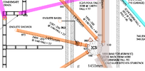
The bottom left is the head of the foul drain run, which terminates in a stub stack to service the new flat roof extension kitchen to be fitted against the leftmost wall in the original image. A 45° connector leads to a short branch and SVP on the external wall close by. The top of the strip foundation, that runs left to right across the back of the existing bungalow, in this location is 125mm below patio FGL (the 1958 concrete is approx 150mm deep).
I thought it might be prudent to get back from that strip found reasonablky quickly and be at least 1metre back so as to avoid concrete drain trench fill to the level of the underside of the existing found.
In order to pick up a possible future air to air heat pump condensate drain on the back wall of the extension (but that is simply water, so is it meant for storm drain) and to add a foul branch from a garden hot tub sunk into a raised garden area, I decided to just keep on going with that drain into the rear patio area.
From what I can tell, the obvert of the (storm) land drain must start at a minimum of 400mm below patio FGL hereabouts. The foul obvert to land drain invert cross point gap is currently only 50mm so would appreciate other options.
Again, the en Suite Bathroom, one 110mm run for the WC and the basin at least could connect to that, possible the shower could too.
So long as I can independently pick up the garden hot tub & future heat pump condensate drains, I can't see a good reason not to place the kitchen stub stack at the far side of the extension and have drawn that possibility on the the pdf. The drain now then runs from there to IC5 45° in (hashed red line) along the same line as the ensuite shower (the less crossings, the better).
However, i'm somehow reminded of this:
connecting to main sewer for ground floor toilet
...[]...
Your solution to drop onto the top of the pipe with a saddle or junction may be ok, but it will depend on the views of the BCO looking at the job. Alternatively, use of a shallow chamber at the appropriate level, then a bend on the outlet to take the pipe down to connect onto the existing sewer may also be an option.
Are you suggesting to drop the ensuite shower vertically (110mm) onto the top of the drain and connect to that via 45° connector and 45° bend? (my understanding was that I would, probably, be required to be able to rod upstream by way of a direct IC connection to the ensuite shower, which this wiould not permit).
Other background:
The bottom of the footing (
edit: "footing" should read as "strip foundation") of the detached (1958) garage is 30mm above patio FGL (sitting proudly exposed). It's approx 100 deep. Garage FGL is 200mm above patio FGL.
The wall gap for the foul run between the garage and extension is 1450mm. I believe the full length of thar drain trench must have concrete fill to the level of the underside of the bungalow foundation.
The gap between bungalow back wall and garage front wall is 1175mm. The invert of foul IC5 main out is at lowest permitted value (1000mm) for 450mm IC. The connection between it and driveway foul IC7 squeezes through this gap but undercuts both garage and bungalow foundations, thus requiring concrete trench fill to the underside of existing bungalow foundation (and "packing up" to the underside of the garage foundation).
The land drain & regular storm drain are combined via IC3 prior proceeding through the garage wall, welll below existing strip found level (thus underpinning required).
All falls for storm and foul in the patio area & garage area are at minimum requirements (1/40 foul & 1/80 storm) and all drain runs appear to achieve minimum required cover. Likewise all IC's in these two areas appear to have IC main and branch inverts / obverts within spec.
The existing bathroom becomes internal. It is extended into the area of the flat roof extension so as the base of its servicing stub stack does not need to go beneath the existing strip foundation of the bungalow's back wall (underpinning avoidance).
The top of the strip foundation of the extension will be at least 1000mm below patio FGL.
The extension floor buildup will be the same as the existing suspended floors. All will be modified to ensure 150mm clear void between top of oversite and bottom of floor joist.
The driveway has 3 distinct average slope regions. Various foul/storm drain falls (at or above minimum) were chosen so as to maintain all drain run obverts 600mm below driveway FGL and IC obvert / inverts between 600mm & 1000mm of driveway FGL.
If possible I do not wish to construct or have a prefabricated manhole (for drain invert of greater than 1000mm) anywhere in the scheme.
If possible I do not wish to have any exterior wall standpipes in the scheme.
Unless otherwise stated figures at IC's are invert values with repect to rear patio FGL.
Two further queries:
a/ It all seems to "fit. However, many/most of the drain crossing points have very little separation between obvert below / invert above - is this an issue?
b/ Again, if nothing is changed from the plan as it is currently stands, are/should/could the 5 input connections (some greater than 45°) to foul IC5 be acceptable?
Again, any comment appreciated.
PS:
the pdf updates zoom on my Win 10 machine in Firefox, Chrome and opera quite quickly so, if anybody is looking, I hope that happens for you too