Anybody used to installing CT's commercially.

Joined
10 Feb 2007
Messages
1,393
Reaction score
40
Location
Cumbria
Country
United Kingdom
I am going for a job interview "CT meter fitter" (already fit meters) and wondered if anybody here has installed whole current CT's on commercial premises.
I know the basics of working out the ratio's but confused about the installation wiring schematics on live systems?

I would get training but want to impress at the interview!

Cheers
 
Sponsored Links
Would you be installing the CTs, or just fitting meters to the CTs?

Are the CTs not installed by the mains lads when they install the cutout?

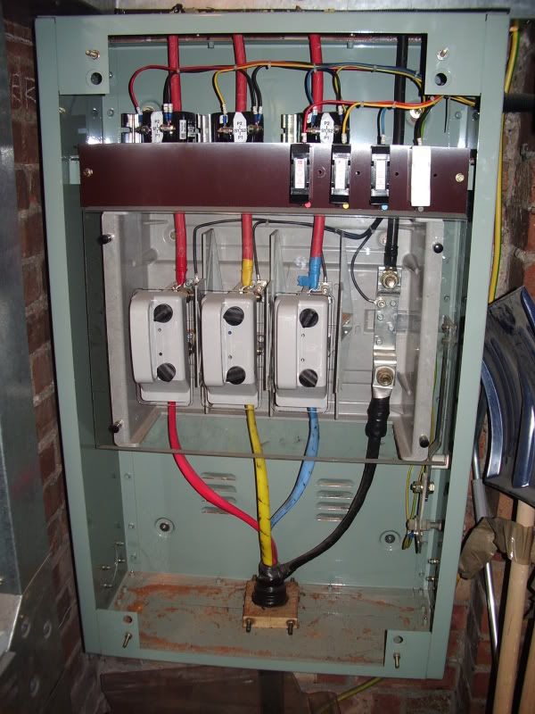
They look like they come pre installed in the cutout.

IMGP2318.jpg
 
RF that looks a full blown premises incomer. Yes C/Ts like that are normally pre-installed at the manufacturers. I used to work for a firm that made switchgear and made our own C/Ts.
 
Sponsored Links
It would be post completion, rather that at the build stage. It would be for current metering using comms for "live" reading on equipment via the web.
I can only assume they would be clip-on CT's, but the diagrams I have seen also use 240vac (L1,L2,L3,N) current as part of the meter operation via breakers?
It would be mainly be mobile phone masts.

http://www.daeinstrument.com/downloads/Dedicated CT-2.1e.pdf
 
We install CT's on all our electrical panels that go out with Hydraulic presses.

We use them with Socomec power meters which can be monitored via a PLC or over a network with the correct modules.

The socomecs have three blocks of terminals;

S1 (L1) S1 (L2) and S1 (L3) + S2 (for connection to the windings of the CT)

V1 V2 V3 Vn for connection to each phase for Voltage and frequency monitoring and probaby more (needs fusing down)

L1 and L2 for the auxillary supply (to power the meter, also needs fusing down)

Matt

How would someone connect V1 V2 V3 VN + L1 L2 to an existing live supply (off the bus bar on new builds). I am assuming they would want no "down time" on their mobile network? Clip-on CT's would not have a problem of course.
Do you set the ratio when you are building. I used to work on building PLC's but have never working in metering fitting area in factory.
Cheers
 
The socomec meters we use can take a maximum of 6A on the input terminals. I think the ratio on the transformers is 120/5A

Its just a matter of making a simple setting in the meter to select the ratio of the CT that you are using.

As far as connecting to a live supply goes no idea, presumably specialist training would be required. Are you really in bahama? Can't see how doing this in the UK wouldnt be in breach of the EAWR

Bahamas....we all need a dream :cool:
 
Word of warning, never open circuit a CT on a live system as you can end up with very high voltages present! This is also the reason that a CT circuit is never fused.
If the output of your CT is too high for the range of the instrumentation then shunt resistors can be placed across the instrumentation so only a portion of the current flows through the instrumentation and the rest through the shunt resistor. The instrumentation will have to be calibrated taking this into account of course.

Ok, I have read this and understand. I would of course have to successfully complete training before fitting any equipment on site.
It would of course mean a mobile phone mast would have to be powered down before working.
I just want some prior knowledge before attending any interview for this engineering job.
 
It depends, those clip on CT coils look like you wouldn't need to power down, just as long as the output of the CT isn't open circuited.
If you need to disconnect to thread a doughnut one on then you'd have to power down as there really isn't any other option.
 
Rob, a quick one, would that CT cabinet happen to be in one of the premises of my employer? ;)
 

DIYnot Local

Staff member

If you need to find a tradesperson to get your job done, please try our local search below, or if you are doing it yourself you can find suppliers local to you.

Select the supplier or trade you require, enter your location to begin your search.


Are you a trade or supplier? You can create your listing free at DIYnot Local

 
Sponsored Links
Back
Top