Backwards Room Stat

Joined
4 Oct 2005
Messages
128
Reaction score
5
Country
United Kingdom
Please Help!!

I've replaced my Drayton roomstat with a Siemens digital one and it's all gone Pete Tong!
The HW is fine but the CH comes on when you turn the room stat down (regardless of what the programmer calls for). Originally it would blow the fuse when the room stat activated but I swapped the wires around a few times. The roomstat wiring is now as follows:
Brown wire from live (Q11) to programmer CH on. Blue wire from neutral (Q14) to neutral in block. Yellow\Green from switched (Q12) to grey on Valve.
I have to witch off the programmer to shut everthing down when I leave the house or the CH will be on perminately.

I have a pumped Y plan.

Any help would be greatly appreciated.
 
Sponsored Links
you should not be using the earth conductor for non-earth purposes. It's confusing and potentially dangerous.
 
Hello Slippy,

I didn't know there was an earth! If you're referring to the cable colours I'm afraid that's whats already there, I'm not going to re-wire the whole thing just to get the colours right, but I agree in principal.

Is that what you meant or is there an earth I'm not using correctly?
 
Sponsored Links
Yellow\Green from switched (Q12) to grey on Valve
Try reading the instructions for wiring a Y plan (Honeywell site). The switched live from the room stat connects to the white wire to the motorised valve.
 
Hello Chris,

I've checked the wiring and I was wrong, the SL does got to the white on the valve - sorry for confusion. :oops:

I'm working on a full diagram to post - may take a while, it's like spaghetti junction.

Thanks for your reply.
 
I don't know the unit you're referring to but you obviously have the white valve connection on the no call for heat rather than the call for heat contact.

Some nitwit seems to have used twin and earth instead of 3 core (black grey brown) and earth.

A simple solution to that is to change the rstat again for one which doesn't require a neutral, use the black (or blue) neutral wire for the call for heat connection and put a bit of red sleeving round it at each end to inform people it is not a neutral.

That is if you can't just re run a fresh cable with correct number of double insulated carriers.

The fact you first blew fuses illustrates my point beautifully.

What a good job it's now important to have sufficient training and test equipment to fart all cavalier switching wire till fuses don't blow.
 
Hi Paul, thankyou for your reply, but I'm still a bit confused, exactly where should each wire go?

On the new Siemens (Landis & Staefa RDD10.1) there are 3 connections:

Q11 - Wiring diagram would suggest this is live (Originally connected to Programmer CH on);

Q14 - Going to a valve symbol on wiring diagram (Originally connected to neutral in block);

Q12 - Wiring diagram does not show this connected to anything but is the other end of switch with Q14 (Originally connected to white wire on valve)

With this configuration the fuse would blow when roomstat called for heat.

I think my problem is I've changed from a really old room stat to a new one and it's not as straight forward as I thought! :(

Any suggestions?
 
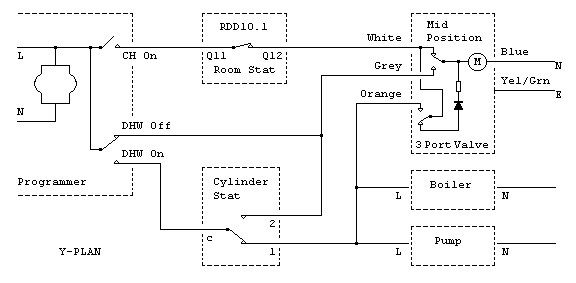
The Siemens RDD10.1 is battery powered, so does not require a Neutral connection. You just need to connect programmer's Switched Live (CH On) to Q11, and connect Q12 (the normally closed control output) to the white wire of the 3-port valve:

rdd101.gif

(Rectifier orientation now corrected)
 
Great circuit diagram, but isn't the diode symbol the wrong way round? The DC current from the diode is meant to stall the motor.
 
Excellent!! :D

Thanks CH4 that looks good. I was unaware you didn't need a neutral with batteries. I've made a digram in Visio of the current wiring and therefore got a better idea of whats going on and what you said makes perfect sense. I'll try it tomorrow and let you know how I get on.

Thanks aswell Chris, you're probably right, I'll crack open the valve motor just to check the diode is pointing in the right direction. :eek: :eek: :eek:
(Seriously, thanks for your help though.)
 
DIYIdoit,
You're welcome!

chrishutt,
Some time ago, I realised that the diode is orientated the other way around in Honeywell mid-position valves, but as I would have had to alter a whole sequence of sketches (used in THIS thread) I left it as it was.

In any case, the diode's function is only to rectify the mains. Whether it blocks the positive or negative half cycles is not important, as the motor's capacitor will not pass DC either way. Hence, the supply to half the motor's windings (those fed by the capacitor) will still be blocked and the motor will stall. So the end result will be the same.

Nevertheless, I've now flipped the diode in the sketch above :)

Cheers,

John
 
I've now flipped the diode in the sketch above
Which now makes my following comment look stupid! :evil:

In any case, the diode's function is only to rectify the mains. Whether it blocks the positive or negative half cycles is not important, as the motor's capacitor will not pass DC either way. Hence, the supply to half the motor's windings (those fed by the capacitor) will still be blocked and the motor will stall. So the end result will be the same.
That's a very interesting point, which I had to think about a bit before I understood it (OK, so I am stupid). But I guess you're right, it doesn't really matter.
 
Hello again,

CH4 thanks for the diagram it worked a treat, the room stat is now functioning properly. :D

However.....

It has highlighted another problem. The programmer is constantly calling for heat whether it's set to off\timed\once\on. If I switch the HW on the valve rewinds to the midway position. If I turn down the tank stat it winds up to the CH position and if I turn down the room stat it rewinds to the HW position (if the tank stat calls). So the tank stat & valve are OK and the programmers OK as far as HW is concerned. If I switch the programmer off at the fuse the valve moves to the HW position. But when the programmer is powered it constantly calls for heat. The boiler responds correctly by the way. The programmer is wired as follows:

Live to fuse brown
Neutral to neutral
1 to valve grey
2 not connected
3 to tank stat brown
4 to room stat brown (Q11)

As far as I can see everthing is OK. Could it be a faulty programmer? It's brand new but has been through several wiring changes these past couple of days, could I have broken it? Its an LP522 btw. Any ideas? Why won't it work? :cry: :cry: :cry:

Thanks in advance.
 
DIYIdoit said:
The roomstat wiring is now as follows:
Brown wire from live (Q11) to programmer CH on. Blue wire from neutral (Q14) to neutral in block. Yellow\Green from switched (Q12) to grey on Valve.

either get a stat that does not require neutral or change the cable for 3C+E. what you have done can be extremly dangerous and kill someone. the earth is only single insulated, not double insulated. do you really want to put someones life at risk to save a few quid
 

DIYnot Local

Staff member

If you need to find a tradesperson to get your job done, please try our local search below, or if you are doing it yourself you can find suppliers local to you.

Select the supplier or trade you require, enter your location to begin your search.


Are you a trade or supplier? You can create your listing free at DIYnot Local

 
Sponsored Links
Back
Top