Bathroom Extractor Fans and FCU's

Thats the point and the problem.

The permanent live to the fan is interupted by the three pole isolator.

Unfortunately I haven't got my drawing package on this computer.
Descriptively:
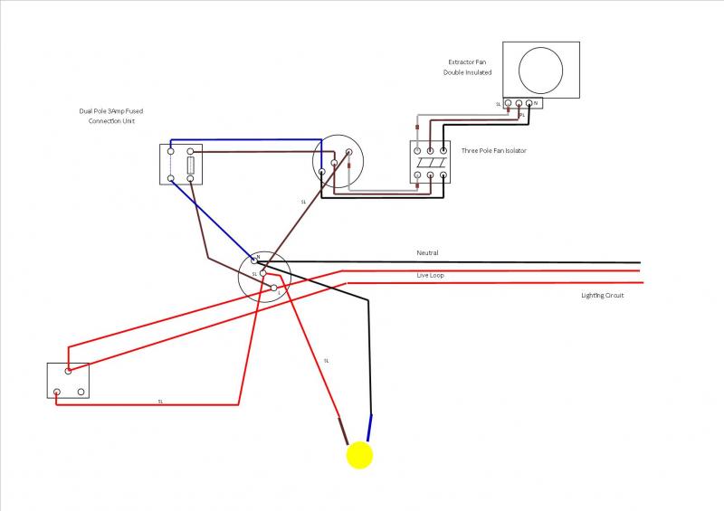
The lights in the bathroom are currently controlled from a jb (they're downlights) which connects the downstairs lighting circuit.

In my proposal, the switch wire comes from the jb permanent live down to the now FCU through the fused side and back out to the switch live terminal at the jb and onto the lights - with the appropriate neutral and cpc. Thus I have introduced a 3 amp fuse into the circuit as required.
The three core fan wire goes from the jb permanent live, switch live, neutral and cpc through a three pole isolator onto the fan. Thus I can isolate the supply to the fan for maintenance but keep the lights running if necessary.
 
Sponsored Links
Thats the point and the problem.
But...
Having given some further thought to this issue - is there anything wrong with replacing a wall switch (just with live, switched live and earth) with a switched single pole 3amp FCU and just using the two live terminals? In otherwords just replacing one switch with another that happens to also have a means of isolation in it.
Together with a three pole isolator this would appear to meet the manufactuer's instructions and reduce the amount of cable and time needed to complete the installation.
Are you now saying that your "is there anything wrong with....would appear to meet the manufacturers instructions..." does have a problem?


The permanent live to the fan is interupted by the three pole isolator.
Yes. That's not the problem.


In my proposal, the switch wire comes from the jb permanent live down to the now FCU through the fused side and back out to the switch live terminal at the jb and onto the lights - with the appropriate neutral and cpc. Thus I have introduced a 3 amp fuse into the circuit as required.
You've introduced a 3A fuse into the switched live to the fan.

The 3A fuse in the permanent live to the fan is where, exactly?
 
If those address all of the concerns that the person who gave my post a thumbs down would you please remove the -ve mark now?

If there's still something else you aren't happy with would you please explain what it is?
Apparently no retractions or explanations will be forthcoming.

What a surprise. :rolleyes:

Note to anyone following this topic now, or reading it in the future:

There's nothing wrong with this: //www.diynot.com/forums/viewtopic.php?p=1814134#1814134 - it got a thumbs down because there's a pathetic immature idiot at loose here who thinks it is funny to give posts negative ratings even though he can't actually find anything wrong with them.
Oh look - the stupid little **** doesn't think I should draw attention to his stupidity.

I wonder if he is so stupid that he can't grasp that the way to make me stop doing that is for him to stop behaving like a stupid little ****?
 
Whoever you are, ****, I'm never going to stop asking you to behave properly - giving me a thumbs down every time I do just proves I am in the right and you are in the wrong.
 
Sponsored Links
The 3A fuse in the permanent live to the fan is where, exactly?
Your good at giving advice BAS but I do wish you would be more specific in you answers. It would save a lot of time (and less cutting and pasting) if you had just said that my proposal would not comply with manufacturers instructions because I had to have the fuse across the permanent live.

Right I will go back to my original plan.
 
Your good at giving advice BAS but I do wish you would be more specific in you answers. It would save a lot of time (and less cutting and pasting) if you had just said that my proposal would not comply with manufacturers instructions because I had to have the fuse across the permanent live.
The thing is you learn more, understand more, and retain more if you work things out for yourself.


Right I will go back to my original plan.
Do you mean this one:


interupting the lighting circuit with a jb taking the line/neutral and cpc which feeds through a FCU onto another jb from which the cable to the switch - switch live to the lights and three core through a three pole isolator to the extractor are linked.
?

If so, then...

Is there another way?
Yes, there is a way which means that you do not end up with the light on the same fuse as the fan, and do not need to add a 3-pole isolation switch.
 
Would it be acceptable to mount 2 fcu's side by side? One for the perm live and one for the switched live?
Yes.
I don't agree with this method, you are only meant to have one 3A fuse - not two.

Back to the OP, your original solution is fine where you have a 3A FCU feeding both the lights and fan, with a 3p isolator for the fan.

Alternatively I think it is usually in the MI where you have a DP switch using one pole for the lighting circuit and the other pole for the fan circuit supplied via its own 3A DP FCU.
 
Is there another way?
Yes, there is a way which means that you do not end up with the light on the same fuse as the fan, and do not need to add a 3-pole isolation switch.

Are you talking about plugwash's diagram of looping the lighting through the SFCU and the fan through the load side as per
//www.diynot.com/wiki/_detail/...hed.jpg?id=electrics:lighting:fan&cache=cache

I did consider it but the way the current wiring system is set up doesn't lend itself to this method. Furthermore the customer doesn't want pull switches in his bathroom. There is a walk in loft above the bathroom that is ideal to complete the wiring as per my initial thoughts.
Thanks
 
Are you talking about plugwash's diagram of looping the lighting through the SFCU and the fan through the load side as per
//www.diynot.com/wiki/_detail/...id=electrics:lighting:fan&cache=cache[/QUOTE]
Well - my diagram, actually: //www.diynot.com/wiki/_media/electrics:lighting:fanwiring7ib.jpg?cache=cache ;)

But yes.


I did consider it but the way the current wiring system is set up doesn't lend itself to this method.
What is it that's the problem?


Furthermore the customer doesn't want pull switches in his bathroom.
DP wall switches are available. Or a 2-gang and switch the fan separately.

Is the problem that you can't drop another cable to the switch?

The customer is OK though with an FCU and a 3P isolator? Where will they be, and where will the cables run for them?


There is a walk in loft above the bathroom that is ideal to complete the wiring as per my initial thoughts.
Fair enough.

Without changing the switch wiring you could still avoid the light on the fan fuse, and avoid the 3-pole isolator, if these things are important to you, by using a contactor
 
I have now had a chance to get into the walk in loft area and examine the lighting circuit to be linked to this extractor fan. The lights are wired in singles with the bathroom switch taking a live loop in and single switch live out.

This diagram is an outline of what I intend to do I would welcome any helpful comments - The T&E and Three Core & Earth have their CPC's removed for clarity - the lighting circuit itself does not have a CPC.

 
Where is the fuse in the switched live supply to the fan?
Thanks for the response BAS - Given the layout on the wiring system I am presented with I would have to rely on the MCB at the board for that.

The other option would be to put the FCU directly in line with the lighting circuit - where it says neutral - live loop. The problem with this is that the way the lighting circuit is wired, if the fuse went then all the lights in three of the four downstairs rooms would go out as well.
 
the lighting circuit itself does not have a CPC.
That and the fact that the circuit is wired in singles with line looped at the switch and neutral at the rose is a cause for concern - just how old is this existing wiring? Is it cotton braided singles in black enamelled slip conduit?

CPCs on lighting circuits have been a requirement for over 40 years, and any wiring that old is well overdue for replacement, whatever it is made of.
 
The lighting circuit is double insulated (e.g. red on red) singles - Around here they stopped putting them in around 1969. This house dates around 1968. The cables look and tested okay.

CPC wise and cable age I have advised the owner of the need to consider an upgrade.
 
Thanks for the response BAS - Given the layout on the wiring system I am presented with I would have to rely on the MCB at the board for that.
Not what the manufacturer specifies.


The other option would be to put the FCU directly in line with the lighting circuit - where it says neutral - live loop. The problem with this is that the way the lighting circuit is wired, if the fuse went then all the lights in three of the four downstairs rooms would go out as well.
Well don't do it that way then.
 

DIYnot Local

Staff member

If you need to find a tradesperson to get your job done, please try our local search below, or if you are doing it yourself you can find suppliers local to you.

Select the supplier or trade you require, enter your location to begin your search.


Are you a trade or supplier? You can create your listing free at DIYnot Local

 
Sponsored Links
Back
Top