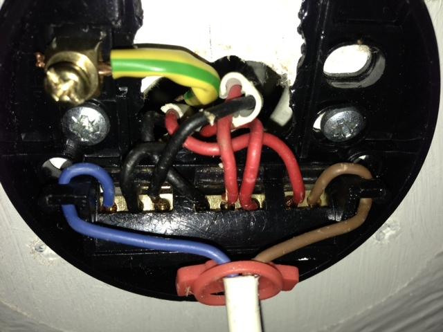
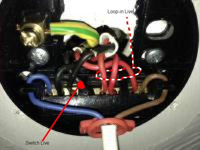
I was wondering if someone could help me understand the wiring arrangement in the picture. I've looked on the wiki about ceiling roses and modern lights. I think I need to put a new junction box in the loft above the rose that replicates the wiring arrangement and then feed a single new three core down to feed the new fitting. But I can't seem to make sense of the wiring to be able to replicate it. Many thanks.