Change 2 1g-2way kitchen light switches so operate normally

Joined
9 Apr 2012
Messages
277
Reaction score
3
Country
United Kingdom
Hi,

I have 2 x 1g-2way light switches in the kitchen.
These control 5 spots on the ceiling which are split into two circuits of 2 spots and 3 spots.

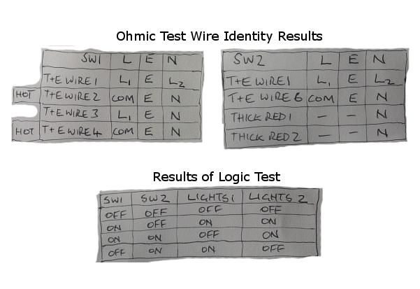
Here are the outputs possible for the switch positions :
1. When both switches ( SW1 & SW2 ) are off all the spots are off.
2. When the kitchen door switch ( SW1 ) is on and the back door switch ( SW2 ) is off all 5 spots are on.
3. When the kitchen door switch ( SW1 ) is on and the back door switch ( SW2 ) is on 2 of the 5 spots remain lit only.
4. When the kitchen door switch ( SW1 ) is off and the back door switch ( SW2 ) is on the other 3 of the 5 spots remain lit only.

They are definitely 1g-2way switches as I have opened them up.
( Thanks to mikeyd and riveralt for pointing out correct switch naming )

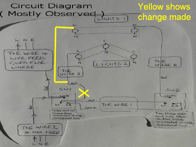
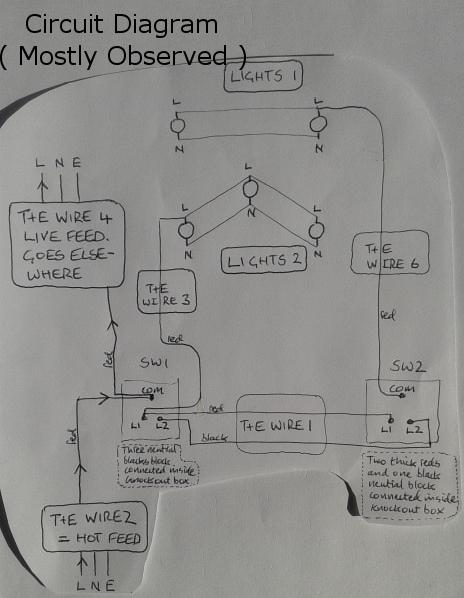
Into Switch 1 there are 4 twin and earth. Switch 1 has two red wires into common, two red wires into L1, only one black wire into L2. Three black wires are joined together in a block connector in the knock out box.

Into Switch 2 there are at least two twin and earth. Switch 2 has red into common, red into L1 and black into L2. Two red wires ( which look to have common designation as they have the old thick red sheath over them ) and a black wire are connected with a block connector inside the knock out box.

Does anyone have the wiring diagram that describes the above.

I want to change this to a straight forward on/off 2 x 1g-2way switch lighting arrangement where all 5 spots are either on or off and this can be achieved with either switch.

Can anyone advise how I can do this with the existing wiring.


Thank you

Kez[code:1][/code:1]
 
Sponsored Links
They are definately 2g switches as I have opened them up.

To me, 2g would stand for 2 gang, i.e. 2 separate switches on one plate. I think you mean you have 2 way switches

Does anyone have the wiring diagram that describes the above.

Standard two way switching diagrams are in the wiki here: //www.diynot.com/wiki/electrics:lighting:two_way_lighting
It's going to be hard to say if/how to do what you want to achieve without knowing which cables go to where. Are you any good with a multi-meter?

The existing setup must drive you nuts though so I can understand why you want it changed.
 
Firstly you don't need to open up the switch to determine whether it is two gang or not you can see from looking at it.

Do you perhaps have a 2way single gang switch at the kitchen entrance and back door - because that appears to be what you are describing when you state which conductor goes into C L1 and L2.

This is a two way single gang switch
http://www.screwfix.com/p/mk-1-gang-2-way-10ax-light-switch-white/11822
This is a two way two gang switch
http://www.screwfix.com/p/mk-2-gang-2-way-10ax-light-switch-white/16201
Which do you have?
 
Hi,

Thanks folks for bringing the clarity.
Apologies for the confusion.
I have 1gang 2 way switches. One beside the kitchen door. One beside the back door.
( original posting above tidied up - hopefully it makes reasonable sense now )

Thanks & regards

Kez
 
Sponsored Links
Hi,

Yes I can use a multi meter.
Yes it drives me nuts.

Thank you and regards

Kez
 
Into Switch 2 there are at least two twin and earth. Switch 2 has red into common, red into L1 and black into L2. Two red wires ( which look to have common designation as they have the old thick red sheath over them ) and a black wire are connected with a block connector inside the knock out box.
Are you saying that the two thicker red wires and the black wire are connected 'Together' in the same terminal block or are they separate - one set of thicker reds in one terminal and the black in the other.
It might be more helpful with a photograph of the both switches showing which switch is which and clearly showing all the conductors.
 
The two thicker red's are connected into the same block connector as the black
 
It might be that of the 4 cables at the first switch: One cable is the supply from your consumer unit, one cable is feeding another room, one cable goes to one set of spots and the other goes to the other switch.
Then at the other switch: One cable might go to the other set of spots and the other cable comes from the first switch.

OR.. Any one of a hundred different combinations. If it is like I describe then you cannot change it to a normal 2 way setup just by re-wiring switches as you would need a three core + earth between the switches.

What is the access like in the ceiling?

I would start by mapping out all the cables. First label all the cables and note what core connects to which terminals on the switches. Then at least you can get it back to how it is now.

Then (assuming you don't have easy access from above), with the power off pull down the spots and work out which one in each of the two groups has the feed.

Then disconnect the wires from the switches and the first spot's in the circuit's and bell them out. So, multimeter on continuity and methodically check which cables are open circuit before joining the red & black of a cable and checking again until you find the other end of the cable.

Any cables in the room you can't find the other end of are likely to be the supply or a feed to another room.

After knowing the results of that: Changing it to a two way setup might be as easy as fishing a cable in the ceiling between the two groups of lights, adding a junction in the ceiling and rewiring switches but it's impossible to know yet.
 
I agree with mikeyd's comments - though I feel there is a junction box somewhere between the lights and the switches.
What concerns me is that the two singles (reds) on SW2 would, under the old singles 1960/70's lighting circuit, have formed the live loop in the common terminal.
Here however they appear to have been linked in the terminal block with the black cable being possibly used as the live back to the L2 terminal on SW1.
At the SW1 switch of the two reds in Common and L1 one set goes to their respective light sets and the other set acts as the strappers back to SW2 - back to C and L1 - but the black in L2??

Good one to get the brain hurting...
 
Hi folks,

Thank you. I have easy access to the space above the lighting area. I don't know whether there is flooring over some of it. There is loads of glass wool and rock wool though. I will have a look and report back.

Does anyone have a circuit diagram which might explain what is happening.
When I discover what is going on I will post the circuit diagram.

Thanks & regards

Kez
 
Does anyone have a circuit diagram which might explain what is happening.
When I discover what is going on I will post the circuit diagram.
It will be difficult to give you a circuit diagram for this particular circuit layout because it seems to contain elements of a two way system in which both lighting circuits are combined and separated.
Furthermore we are not sure how they are connected together outside the switches.
As suggested probably the simplest solution will be to identify the switch live, neutral and earth cables that go to the two sets of lights in the access space and join them in a junction box so that the switches operate as you want them to do.
So identify the cables that link each set together - follow them back until you have both together. Hopefully there will be a bit of slack then, with the power off, cut and join them together in a junction box. Switch live to switch live, neutral to neutral and earth to earth.
You will probably need a 4 way 30amp junction box to give you sufficient space to house what will become four cables.
 
Mikeyd, Not wishing to contradict as obviously you know what you are thinking, however, 3 core and earth is not the only way to do two way lighting. It is possible (but by no means certain) that the OP has a two core and earth between the switches to achieve a simple two way system.
 
Results :

Folks. Here is the circuit. I got it by carefully analysing the contents of the knock out boxes behind the switches, and doing ohmic tests across all combinations of the wires in both knock out boxes SW1 and SW2, and looking at the connections to the lights in the loft.


I did a map of the ohmic tests as shown below and then did a brain test to check the drawn circuit produced what was observed.

It did so I pulled TWIN+EARTH WIRE 3 through to the loft and connected it to circuit LIGHTS 1. Yellow below shows this simple change. Connected all switches back up and every thing functioned as 2-way switching is intended to work. :). Replaced old switches with new MK's and very happy ! :)


Thank you everyone for all your help.

I am very grateful,

Kind regards

Kez
 

DIYnot Local

Staff member

If you need to find a tradesperson to get your job done, please try our local search below, or if you are doing it yourself you can find suppliers local to you.

Select the supplier or trade you require, enter your location to begin your search.


Are you a trade or supplier? You can create your listing free at DIYnot Local

 
Sponsored Links
Back
Top