You have somewhat lost me with all of this.
There are three Photos.
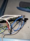
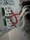
1 - a "mess" of wires and connectors
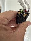
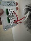
2 - a batten holder with Line (Red), Neutral (Black) and Earth (Green/Yellow) cable connected
plus a single (Black) Neutral conductor.
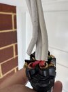
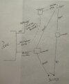
3 - a batten holder with a Cable with two Red insulated conductors, another single Neutral (Black) conductor
and who knows what behind, which cannot be seen
(which seems to be a
different bittern holder ?)
A cable with Red and White insulated conductors is the normal Australian Switch Loop connection, for Line and Switched line respectively.
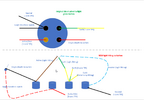
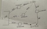
The photo below shows the "normal" Australian (switched) batten holder connections - (rather badly)
Login

www.lighting-gallery.net
The incoming (Red) Line conductor is connected in the "Loop" terminal,
together with the (Red) Line conductor
to the Switch.
The (White) Switched-Line conductor
from the Switch connects to one of the bayonet Contact Pin connections in the bittern holder.
The (Black) incoming Neutral conductor is connected to the
other bayonet Contact Pin connection.
The Green/Yellow Earth conductor is connected to the (pseudo) "Earth" terminal - which goes nowhere, since this device is all plastic and does
not require "Earthing".
Your new fitting will need to have
the incoming (Red) Line conductor connected to the (Red) "Line" conductor
to the Switch - using an appropriate connector.
The (White) Switched-Line conductor
from the Switch must connect to the Line (probably Brown) conductor of the Limp fitting.
The incoming (Black) Neutral conductor connects to the Neutral (probably Blue) conductor of the Lamp fitting.
The (Green/Yellow) incoming Earth conductor connects to the Earth (?) connection of the Lamp fitting.