Consumer Unit Replacement

Flange couplers usually come with a 20mm serrated washer or if you want them, likely sold on ebay
Flanged couplers are not supplied with serrated washers but just the lead washer. If you wanted serrated washers you would have to purchase them separately.

Flanged couplers are always used here when entering accessories/trunking.
 
Sponsored Links
Why?

Seriously, why, why why?

You really ought to examine why, and join in a discussion here, because there is a very good chance that you are mistaken in your reasons for wanting one, and are ignorant of all the reasons why you should not want one.

You could start by searching the forum for previous discussions of smart meters.

OK thanks for that I will take a look and join in as I have not given it much if any thought as you probably guessed already, which is the reason I have never had it installed until now.
 
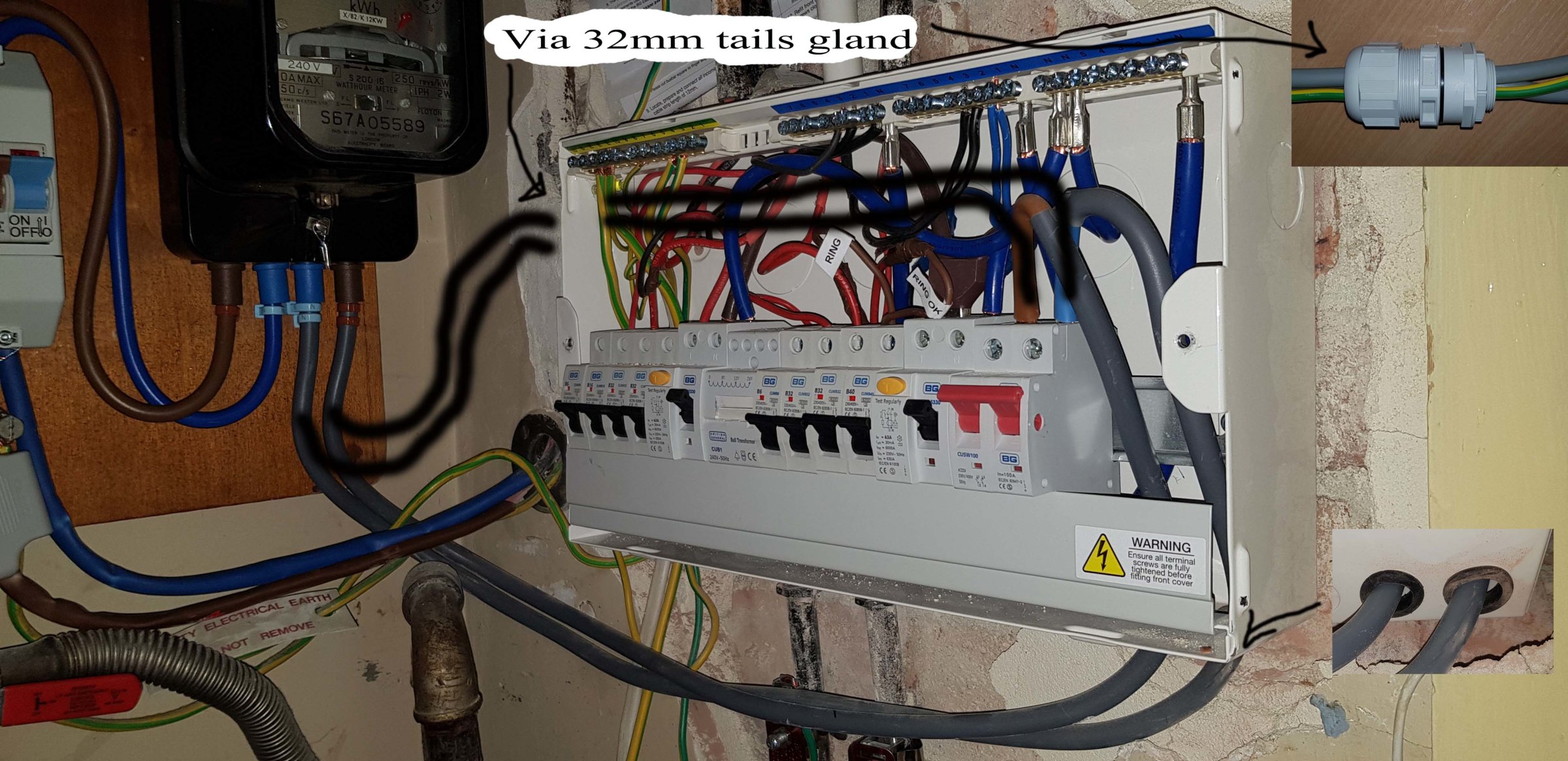
I was wondering if its OK to move the tails entry as currently having each tail coming in via separate 20mm holes isn't allowed I believe as mentioned by Sparkwright earlier on, although I didn't realise fully until watching a video last night about heating due to eddy currents. although the video proved for domestic electrics it isn't a problem as he demonstrated but stated that exit and entry cables for the same circuit should go through the same hole.
I don't really like the way the tails cable go all the way along the CU and was wondering about putting them in from the side using a tails gland kit and then running them at the back of the CU to the switch.
There wouldn't be such a tight bend on them entering the main dual pole switch anymore.
Previously ?I suggested moving the switch to the left but was advised against it by Sparkwright so I would leave it on the right where it currently is.
Would this be OK ?


The only catch I can see with this idea at the moment is the amount the tails gland sticks out from the CU, as also need extra space for the tails to bend as well.
All the kits seem to be 40mm and come with 32mm reducer but the 32mm reducer adds to the length :(
 
Last edited:
Yes both tails must enter the same hole on a metal CU. I would also put the main earth through the same hole too. It's acceptable to cut a thin slot between the holes also, that makes it electrically one hole.
 
Sponsored Links
having each tail coming in via separate 20mm holes isn't allowed
There is no explicit prohibition of it.


although the video proved for domestic electrics it isn't a problem as he demonstrated
Exactly.


but stated that exit and entry cables for the same circuit should go through the same hole.
Even though nothing mandates that, and even though not doing it demonstrably causes no problems.


I don't really like the way the tails cable go all the way along the CU
What is it you don't like?


and was wondering about putting them in from the side using a tails gland kit and then running them at the back of the CU to the switch.
There wouldn't be such a tight bend on them entering the main dual pole switch anymore.
There's nothing wrong with the bends, and running them inside as you propose could well mean that they get in the way.
 
I would also put the main earth through the same hole too.
I was just thinking about whether this also applies to bonding , if your MET is inside the CU. Apparently the associated CPC must also enter the same hole, but no mention of bonding. If the bonding is carrying currents (e.g. in a PME system) then I'd expect it to be entering via the same hole.

I'm assuming that the chances of a faulty shower passing a high current to the metal pipework for long periods would be discounted. Otherwise you'd have to have every single cable entering through the same hole!

Any thoughts?
 
Watch the video and at 5:45 near the end he says going through different holes doesn't comply with BS7671.
yes, apparently 521.5.1 is the reg, but I haven't worked out if it applies to bonding as well as the circuit conductors
 
What is it you don't like?

Well I am just not too keen on them running loose under the CU as I think its possible they could get caught on something in the cupboard and yanked. Since they are loose so to speak and the grommits could easily fall out thus allowing the insulation to be cut by the CU knockout hole if yanked.

There's nothing wrong with the bends, and running them inside as you propose could well mean that they get in the way.
Very true and I have thought of that but the CU is quite deep although with the switch on the right it is definitely much more of a problem. Hence the reason earlier on in this thread I suggested moving the switch to the left hand side of the CU but was told that it is not recommended. I am not sure why, I thought quicker access to switch off maybe ?

I just thought if I used this tails gland kit it would secure the cables and waterproof it not that water is a problem if entering from below due to gravity.
 
I was just thinking about whether this also applies to bonding , if your MET is inside the CU. Apparently the associated CPC must also enter the same hole, but no mention of bonding. If the bonding is carrying currents (e.g. in a PME system) then I'd expect it to be entering via the same hole.
I really can't see why (when the MET is inside the CU) a main bonding conductor needs to (or should) go through the same hole as the tails. On the contrary, I can see a theoretical argument why it should not go through any hole in a metal enclosure at all (with or without other conductors)!

If high currents were to flow in a bonding conductor, it would presumably be from the provided earth (TN or TT) to an extraneous-c-p. That is a 'one conductor' situation, with no other conductor carrying a 'balancing return current'. Hence if it went through any hole in a metal enclosure, with or without other conductors, it would induce eddy currents in the metal - which, as I said, could be used to argue that a main bonding conductor should not go through any hole in a metal enclosure.

With a CPC its different, at least conceptually. If there is an L-CPC fault on the circuit, then the return current is shared between N and CPC - and the N+CPC currents should then be equal to, hence 'balance out', the current in the L conductor. Of course if there is an L-E fault that does not involve the circuit's CPC, then the L and N currents will be unequal (and CPC current zero), so there will be a 'unbalanced' current inducing eddy currents into the metal, even if L+N+CPC of the circuit all go through the same hole.

There is a similar argument for the incoming earth to go through the same hole as the tails - since, again, an L-CPC fault anywhere in the installation will result in return current being shared between the N tail and the incoming earth, theoretically with N tail+earth currents being equal to L tail current.

Having said all those theoretical things, I would not have thought that high currents in either CPCs/Earthing Conductors or Main Bonding conductors are likely to persist for long enough for the effects of eddy currents to be an appreciable concern.

Kind Regards, John
 
... I suggested moving the switch to the left hand side of the CU but was told that it is not recommended. I am not sure why, I thought quicker access to switch off maybe ?
The main switch will normally be connected to the device(s) adjacent to it (RCD or non-RCD protected MCBs, or RCBOs) by a bus bar. If the Main Switch bears L and N markings, if you installed the Main Switch on the side of the CU which was not intended, you would have to use the two sides of the switch (L & N) opposite to the way in which they were labelled (e.g. you would have to connected the incoming L tail to the N terminal of the switch. Whilst taht would all work OK, it's not very satisfactory.

Kind Regards, John

Thanks John for that very clear explanation, it makes very good sense.
In the case of my CU the main switch has no N or L markings and it connects to the adjacent RCD via a cable not a bus bar. The cable has a tee connector to allow it to continue on to the 2nd RCD.
So in theory I could move the switch to the left but the RCD's would still need to remain on the right because of the bus bar connecting it to its MCBs.
 

DIYnot Local

Staff member

If you need to find a tradesperson to get your job done, please try our local search below, or if you are doing it yourself you can find suppliers local to you.

Select the supplier or trade you require, enter your location to begin your search.


Are you a trade or supplier? You can create your listing free at DIYnot Local

 
Sponsored Links
Back
Top