Could you check my CH layout please

Joined
12 May 2018
Messages
175
Reaction score
5
Country
United Kingdom
Hello all.
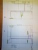
So I've drawn up what I think my CH layout should be. Could you have a look over it and tell me if it's sh1te or if there's something i should do differently please? It is not to scale, but close enough.
The key is at the bottom, but basically the red and blue is 22mm flow and return and the colours coming off those are obviously 15mm to the rads.
Downstairs it's joists on small brick pillars so I intend to mount them underneath the joists, upstairs in the floor void I'll go through the joists (to regs).
The small box on the plan the 22mm appears from, upstairs and downstairs is an 8" x 10" box running up the corner of the utility room perfect for the pipes and elecs to run up.
Thanks everyone, appreciate any ideas/critiscim you could share. :)

Alex

Edit: no taking the p1ss out of my drawings!!! :D:D
 

Attachments

  • 20180609_224744.jpg
    20180609_224744.jpg
    233.4 KB · Views: 328
Sponsored Links
Read up on head loss/flow rates....you can probably loose a lot of that 22mm pipe. Is this a new system including a new boiler? If so you'd size everything based on a 20 degree drop across your flow and returns and therefore your water flowrate is halved, headloss lower and hence pipe size reduced. Where rads are back to back either side of a wall can you not cross the wall?
 
Yes, new boiler, new UV tank, new pipework, new rads.
I'd decided to go a bit further with 22 figuring it would be better for the flow? I've also got a load of 22mm armaflex pipe and as yet no 15mm pipe insulation lol.
Would you suggest I didn't then?

Edit forgot to answer your question about the back to back towel rads...... Yes I could go one to the other, but again I didn't know if it would be preferential to run separate feeds/returns? I am happy to do whatever is the 'best' way of doing it, the extra work doesn't matter.
 
Last edited:
There are recommended flow velocities and oversizing pipework can result in too slow velocities.
Back to back pipework is cheaper but that might not be of concern.
 
Sponsored Links
Morning pal.
So I did some reading last night, indeed a LOT more to the pipe work than I had appreciated. It's great fun learning all the ins and outs:)
I'll have to sit down this evening and get a pen and paper out and work the maths out.
Need to find out the flow rate from the boiler pump first. Anyone know what the l/s of an eco rf 24 is off the top of your head?! Haha.

One question indie have, was I didn't come across much info on the head element. The pipe flow was talked about a lot but not so much the head pressure. Has anyone got any good sites they have come across to read?
Essentially the boiler will be mounted at head height, and the radiators upstairs are all to mounted at the same height so the head can be worked out, but I suspect the height it will move water about itself will only be in the region of 1.5/2 metres.

Alex

Edit: Not that money is no object, but the few quid for running new 15 to each separate rad that is back to back isn't worth a worry. If it's better to separate the feed and return I will do. Means I can isolate each rad that way too for any further works or rad changes etc.
 
Last edited:
no taking the p1ss out of my drawings!!! :D:D
Normally I wouldn't; but do you realise that one rad has no pipes connected to it?

You have 11 rads. Do you know the required output of each one? If so, this will tell you what the boiler needs to produce for CH. (I assume you have a 24kW boiler so the HW cylinder is heated up quickly.) The pipes need to be sized for the CH requirement and assumed temperature drop.

Sizing of radiators:The heat loss of a room is one factor, but you have to take into account the flow, return and room temperatures when sizing rads. This is because the output of a radiator is not fixed (like an electric fire), it varies with temperature.

You mention the Eco RF24, which is a combi boiler, but show an UV cylinder next to the boiler. Is this correct?

The required CH flow rate is Total CH requirement/(4.18 x 20) litres/sec. This formula also applies to the flow rate through a rad; so a 1.5kw output rad needs 1.5/(4.18 x 20) = 0.0179 litres/sec or 1.076 litres/min.
 
One question indie have, was I didn't come across much info on the head element. The pipe flow was talked about a lot but not so much the head pressure. Has anyone got any good sites they have come across to read?
Essentially the boiler will be mounted at head height, and the radiators upstairs are all to mounted at the same height so the head can be worked out, but I suspect the height it will move water about itself will only be in the region of 1.5/2 metres.
"Head" has nothing to do with the vertical height between boiler and rads. It a measure of the pressure loss round the heating circuit due to friction in the pipes, which depends on the pipe size and flow rate.

I have attached two files. Pub-150 explains how to calculate the head (be aware that it assumes a temperature differential of 11C); and Small bore deals with the sizing of pipes and water velocity (not the same as flow rate)..
 

Attachments

  • pub-150-copper-tubes-in-domestic-heating-systems.pdf
    150.5 KB · Views: 813
  • Small-bore-heating-systems.pdf
    64.7 KB · Views: 325
Normally I wouldn't; but do you realise that one rad has no pipes connected to it?

You have 11 rads. Do you know the required output of each one? If so, this will tell you what the boiler needs to produce for CH. (I assume you have a 24kW boiler so the HW cylinder is heated up quickly.) The pipes need to be sized for the CH requirement and assumed temperature drop.

Sizing of radiators:The heat loss of a room is one factor, but you have to take into account the flow, return and room temperatures when sizing rads. This is because the output of a radiator is not fixed (like an electric fire), it varies with temperature.

You mention the Eco RF24, which is a combi boiler, but show an UV cylinder next to the boiler. Is this correct?

The required CH flow rate is Total CH requirement/(4.18 x 20) litres/sec. This formula also applies to the flow rate through a rad; so a 1.5kw output rad needs 1.5/(4.18 x 20) = 0.0179 litres/sec or 1.076 litres/min.

Aye, I'd noticed I'd uploaded my first pic I'd taken, I subsequently added the piping and the measurements in case it helped. Decided it wouldn't matter and you could see what it would be connected to.
Yeah the intergas eco 24 is able to run as a system boiler as such, so will be running the UV tank.
Yes I do have the specs on the new rads so I can use them in the calcs, which many thanks for the total CH equation! Appreciate that. I'll have to sit and work it out later. :)

Alex
 
Afternoon all.
Many thanks to everyone that chipped in, as always it's really appreciated.
I've done some reading this last few days into the flow and head...... wowsers there was so much more to pipes than i ever knew! Been really interesting reading actually, made my little bit of grey matter that's left start working again.

The calcs I did (with a few variable figures) were showing that it could almost all be done in 15mm.
In D_Hailsham's link to small bore heating systems, it suggests 15mm with a temp diff of 20 (which mine should be as Gasguru rightly pointed out) can carry between 3.6 and 18kw depending on velocity.
Now just my radiators alone both upstairs and downstairs totals 12.5kw. So this would suggest my 12.5kw would in fact be fine on 15mm and at about 1.0 to 1.2m/s
This will be in plastic if it makes much difference, all the sizing info pages are pretty much based on copper from what I found.

I guess I'm just looking for confirmation that my thinking/workings are right as the amount of posts I've read that say 15 for flow and return is daft and should always be 22 etc etc etc is enormous. I asked my gas man who came to cap the gas supply yesterday and he said 22 as close to every radiator you can......
With 15 in seems I'm likely to actually get the 20 degree drop as well.

Any help is again much appreciated. Thanks again to Mr Hailsham for those links. I have very much "been down the rabbit hole" on central heating pipes this week thanks to them! Haha.


Alex
 
This will be in plastic if it makes much difference, all the sizing info pages are pretty much based on copper from what I found.
It could make a difference. The velocity is inversely proportional to the internal radius of the pipe so, if the plastic pipe has a narrower bore than the copper the velocity will be higher. The pipe manufacturers will, hopefully, publish the data. You will also need data on the equivalent lengths of the plastic joints etc.

You mention a total rad size of 12.5kW. Is this the heating requirement of the house or the manufacturer's quoted output?

The latest guidance (attached) recommends a return temperature below 55C, to maximize the condensing feature of the boiler. If we assume a return of 50C and flow of 70C, a radiator will only produce 70% of the quoted output, so you will have to install a nominal 1.4kw rad to produce an actual 1kW of heat.
 
Hello mate,
Yes I'd read from one of your posts on another thread from a while back about that. Thankfully, I have oversized my rads anyway to help the boiler condense, so they are all 23-35% bigger than they need to be. Lucky really as i've already bought them before i discovered the pipe intricacies.
I had used several room heat loss calcs, the best I think being the Myson one which then have me a kw/btu target. I then bought the radiators based on this. I didn't realise the pipes would play their part in all of this!
So the rads I have bought total 12.5kw. However the house calcs are less than this.
I was going to use Hep for the heating unless you recommend something different so I'm sure I can find the pipe specs. I'm not sure I fancy going through all those calcs again though!! Haha.

Many thanks as always.

Alex
 
So the rads I have bought total 12.5kw. However the house calcs are less than this.
So the actual heat requirement is about 9.5 to 10 kW. The Intergas Eco RF 24 modulates between 6.1 kW and 18.2 kW which means that, for most of the year, the boiler will be running in on/off mode at minimum output. This will occur if the outside temperature is above approx 7C.

As for Hep pipe (presumably Hep2o), I have no personal experience of the product. However, the internal bore of Hep2o is smaller than the equivalent size copper pipe, so pressure loss is greater. I have attached the Hep2o technical manual, which gives details of the equivalent lengths on pages 60 and 63.
 

Attachments

  • Hep20_Technical_handbook.pdf
    5.2 MB · Views: 424
excellent advice, the only thing I can contribute from a restriction point of view is that the plastic pipe has a smaller bore but you hardly need to use any elbows, so that counteracts the resistance to some degree.

The resistance/flow velocity gets disproprtionately higher on a smaller pipe due to the cross section getting smaller by the square of the radius. Furthermore, the perimeter only goes down linearly, so you get more friction/head loss even at the same flow velocity.

I added a load of new rads here and replaced/moved some of the existing, and due to the boiler ending up in the middle of the house after the extension I ended up using a manifold on each floor fed by 22mm and piping to pretty much each rad in 15mm or 10mm spider fashion. Due to the layout it didn't cost a massive amount of extra pipe and will allow zoning in future without having to use battery trvs. I'm not sure that setup would work for everyone though or be necessary.
 
So the actual heat requirement is about 9.5 to 10 kW. The Intergas Eco RF 24 modulates between 6.1 kW and 18.2 kW which means that, for most of the year, the boiler will be running in on/off mode at minimum output. This will occur if the outside temperature is above approx 7C.

As for Hep pipe (presumably Hep2o), I have no personal experience of the product. However, the internal bore of Hep2o is smaller than the equivalent size copper pipe, so pressure loss is greater. I have attached the Hep2o technical manual, which gives details of the equivalent lengths on pages 60 and 63.

Yes I figured it might be a bit low for the boiler, but sadly the rf24 is the smallest of the 3. However, running in open therm I'm hoping the boiler will modulate down and stay at a low output.
Hot water wise it won't be on a great deal if at all.
It also won't be the sole heat provider, we have a lot burner going in between the two main downstairs rooms, so in the autumn or maybe spring the heat from the log burner will shut the boiler down, so fingers crossed the boiler will be mainly used in winter conditions, which *might* cut the 'on/off period to a minimum.
Muchos gracious for the specs, I just spent some time crunching the numbers again and it's actually done me a favour, in that I can run a 22 f+r for a branch into the downstairs and upstairs and it brought my flow to 1.1m/s which is almost the holy grail lol.
Thanks so much for all the advice! Genuinely couldn't have done it without you all :)

Alex
 
dunno about all this velocity and sheet, but from a practical point of view those rads that are back to back upstairs, you could probably go under the wall there and save yourself lifting the carpet / floor, you never know it might save you some linear flow velocity...or something
 
Last edited:

DIYnot Local

Staff member

If you need to find a tradesperson to get your job done, please try our local search below, or if you are doing it yourself you can find suppliers local to you.

Select the supplier or trade you require, enter your location to begin your search.


Are you a trade or supplier? You can create your listing free at DIYnot Local

 
Sponsored Links
Back
Top