I live in a tenement flat and the door entry handset has never been great, but recently it really got worse. Ever since we moved in 10 years ago the handset speaker and mic has not worked - we could not hear visitors at the panel by the main door, nor could they hear us. We put up with this for ages but then recently it stopped buzzing when visitors pressed our button on the panel. At no point since we've moved in 10 years ago has the wiring been changed.
I thought it must be the handset that's the issue, as my neighbours' handsets were all working fine. According to www.intercomsrus.com it's an Urmet 1030 or 1130, so I got a new Urmet 1130/16 as a replacement. I installed it according to the instructions that came with the handset, but the buzzer still does not buzz when someone presses the panel button. It still has the same issue. This time though I can hear people at the panel, and they can hear me – so that's an improvement : ) Weirdly, the buzzer does actually buzz if the handset is lifted up when someone buzzes, but not when the handset is sitting on the main unit (not sure if this was the case with the old handset).
Have I made a mistake wiring the new handset? Was the old wiring wrong? Or is it an issue with the panel or wiring between the panel and the handset? Or something else maybe? No idea.
Old handset cover plate, Urmet 1030 or 1130, not sure:

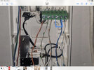
Old handset wiring:

According to www.intercomsrus.com, both 1030 and 1130 have the same terminals (I've noted the wire colour in square brackets)
6, 11, 10 - common [blue wire with white stripes]
2 - speech out (mic) [white wire with orange stripes]
9 - lock [white wire with blue stripes]
7 - call [white wire with green stripes]
1 - speech in (speaker) [orange wire with white stripes]
New handset, Urmet 1130/16:

The terminals on the 1130/16 are definitely different from the old handset. The instruction booklet that came with the handset states the terminals are as follows:
1 - Incoming speech signal (loudspeaker) [orange wire with white stripes]
CA - Call tone by buzzer or electronic [white wire with green stripes]
2 - Outgoing speech signal (mic) [white wire with orange stripes]
6 - System ground
10 - To be connected to the door phone terminal pin 6 [blue wire with white stripes]
9 - Door opener [white wire with blue stripes]
(I tried connecting the blue wire (the system ground / common wire) to terminal 6 but this results in the door lock button not working)
Going a bit crazy here! Would appreciate any help, thanks.
I thought it must be the handset that's the issue, as my neighbours' handsets were all working fine. According to www.intercomsrus.com it's an Urmet 1030 or 1130, so I got a new Urmet 1130/16 as a replacement. I installed it according to the instructions that came with the handset, but the buzzer still does not buzz when someone presses the panel button. It still has the same issue. This time though I can hear people at the panel, and they can hear me – so that's an improvement : ) Weirdly, the buzzer does actually buzz if the handset is lifted up when someone buzzes, but not when the handset is sitting on the main unit (not sure if this was the case with the old handset).
Have I made a mistake wiring the new handset? Was the old wiring wrong? Or is it an issue with the panel or wiring between the panel and the handset? Or something else maybe? No idea.
Old handset cover plate, Urmet 1030 or 1130, not sure:
Old handset wiring:
According to www.intercomsrus.com, both 1030 and 1130 have the same terminals (I've noted the wire colour in square brackets)
6, 11, 10 - common [blue wire with white stripes]
2 - speech out (mic) [white wire with orange stripes]
9 - lock [white wire with blue stripes]
7 - call [white wire with green stripes]
1 - speech in (speaker) [orange wire with white stripes]
New handset, Urmet 1130/16:
The terminals on the 1130/16 are definitely different from the old handset. The instruction booklet that came with the handset states the terminals are as follows:
1 - Incoming speech signal (loudspeaker) [orange wire with white stripes]
CA - Call tone by buzzer or electronic [white wire with green stripes]
2 - Outgoing speech signal (mic) [white wire with orange stripes]
6 - System ground
10 - To be connected to the door phone terminal pin 6 [blue wire with white stripes]
9 - Door opener [white wire with blue stripes]
(I tried connecting the blue wire (the system ground / common wire) to terminal 6 but this results in the door lock button not working)
Going a bit crazy here! Would appreciate any help, thanks.
Last edited: