

Hello, I am trying to replace a Danfoss system with the Drayton Wiser 3 zone setup.
The house currently has a gas boiler controlled by Danfoss TP9000MA which controls the heating downstairs and hot water. This box has an external temperature sensor on the wall which is wired back to the unit. Upstairs there is another Danfoss unit which is battery powered by contains two signal wires which link back to the wiring centre to control the upstairs heating circuit.
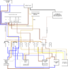
I have traced as much wiring as I can including doing continuity tests from the wiring centre back down to the wiring by the boiler. Diagram:

Existing backplate:

Existing wiring diagram for backplate:

Based on that, I have disconnected 5 and 6 from the unit to remove the downstairs external temperature sensor.
Upstairs this is the back of the thermostat:

I have traced back and continuity tested the brown and black wires and have removed them from the wiring centre. Brown was joined to the right side of 1 in the wiring center. Black was joined to the left side of 7. In its place I have inserted a brown link cable from the right side of 1 into the left side of 7 to create a permanent loop - effectively deleting the thermostat.
Back downstairs at the faceplate I have swapped it over to the new one but with the following changes:
4 on the old faceplate was heating on, this has been moved to heating 3 on the new plate (heating channel 3)
3 on the old faceplate was hot water on, this has been moved to 2 on the new plate (hot water)
The live which went back to 1 on the wiring centre has been moved into 1 on the new plate (heating channel 1)
The last two lives (boiler flex plus one solid live) have been placed in L
The blue neutral wires have been placed in N
The problem is, the downstairs loop is no longer working. Wiser will control the upstairs loop fine, but downstairs doesn't seem to work.
Wiring diagram from the Wiser kit:

Hot water tank and wiring centre:

I think this is possibly down to the wiring centre being non-standard and not matching the requirements of the Wiser setup, but unsure. Any suggestions would be greatly appreciated")
The house currently has a gas boiler controlled by Danfoss TP9000MA which controls the heating downstairs and hot water. This box has an external temperature sensor on the wall which is wired back to the unit. Upstairs there is another Danfoss unit which is battery powered by contains two signal wires which link back to the wiring centre to control the upstairs heating circuit.
I have traced as much wiring as I can including doing continuity tests from the wiring centre back down to the wiring by the boiler. Diagram:
Existing backplate:
Existing wiring diagram for backplate:
Based on that, I have disconnected 5 and 6 from the unit to remove the downstairs external temperature sensor.
Upstairs this is the back of the thermostat:
I have traced back and continuity tested the brown and black wires and have removed them from the wiring centre. Brown was joined to the right side of 1 in the wiring center. Black was joined to the left side of 7. In its place I have inserted a brown link cable from the right side of 1 into the left side of 7 to create a permanent loop - effectively deleting the thermostat.
Back downstairs at the faceplate I have swapped it over to the new one but with the following changes:
4 on the old faceplate was heating on, this has been moved to heating 3 on the new plate (heating channel 3)
3 on the old faceplate was hot water on, this has been moved to 2 on the new plate (hot water)
The live which went back to 1 on the wiring centre has been moved into 1 on the new plate (heating channel 1)
The last two lives (boiler flex plus one solid live) have been placed in L
The blue neutral wires have been placed in N
The problem is, the downstairs loop is no longer working. Wiser will control the upstairs loop fine, but downstairs doesn't seem to work.
Wiring diagram from the Wiser kit:
Hot water tank and wiring centre:
I think this is possibly down to the wiring centre being non-standard and not matching the requirements of the Wiser setup, but unsure. Any suggestions would be greatly appreciated
")
