Electricians' discussion about Intermediate Switches (split off from DIY thread)

Joined
20 Feb 2017
Messages
937
Reaction score
143
Location
Melbourne, Australia
Country
Australia
"Analyzing" this "Problem" has been an "Interesting" exercise for a Summer Sunday afternoon - in Australia!

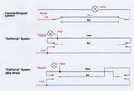
I apologize for using "Americanisms", but I am used to having 2-Way circuits in Australia wired as for that which is called in North America a "Traveler System" but it seems that in the UK this is called a "Strapper" System - as shown in the first diagram below.

I suspect that the circuit is wired as what is called in North America as a "California System", which I understand may be fairly "normal" in the UK and shown correctly wired in the Second Diagram below.
(See https://en.wikipedia.org/wiki/Multiway_switching )
What is that System called in the UK?
Two Way001.jpg
One advantage of this second (California ?) system is that the Lamp could be connected at either end.
In North America, Energy (often miscalled "Power") could also be derived for a 15 A/120 V Socket Outlet at the "far" end, if a Neutral is also available there !

The second diagram above shows a correctly wired "California" System and
the third diagram shows the same system wired incorrectly - giving the problems encountered by pmartin008 ,
with the Lamp and Supply Line connected at the "Landing" and the "Dimmer" SPDT Switch at the "Ground Floor".
(The "Named" Colors of the wiring insulation is immaterial, except to indicate the possibility of reversal.)
Two Way002.jpg
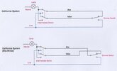
The above two diagrams show the "Complications" introduced by using a "Crossover/Intermediate" switch to do the job of a SPDT switch.

So, reverse the connections of the Blue and Yellow insulated wires at ONE end and it is likely that the problem may be solved !

Why the original "installer" used a (Relatively Expensive) "Intermediate/Crossover" switch,
in lieu of a SPDT switch
(which would have "done the job" for only a 2-Way [2-Location] switching situation)
is incomprehensible!
 
Last edited:
Sponsored Links
two-way-plus-inter.jpg
The two way system shown has one wire that passes through the intermediate switch back box but is not connected to the intermediate switch. The two red wires in the one connector seems wrong. However I don't know where the wires go at other end.
 
OK.
BUT
please review Post #18
All the diagrams you show are two switch systems, the intermediate switch can be used as a two way switch, but in the UK the intermediate switch only has 4 terminals and can't possibly be configured as you show. So as a two way switch one terminal is not used. It seems I may have made an error I have not seen an intermediate switch used as two way with a single gang switch, it is used where one has two gang switches as unless fitting grid switches you can't get a mixture of two way and intermediate, but with a single switch normally one would use a two way as cheaper.

I would have expected to see the red on it's own which was part of the red, yellow, blue. And the red, and black of other cable going with blue and yellow. Does not matter which goes with which, but if the red was in L2 then would expects blue+black in L3 and yellow + red in L4 if the intermediate switch is used as a two way, and L1 empty.
You wrote "The intermediate switch only has 4 terminals and can't possibly be configured as you show."
Oh!. Yes it can be so configured.
It is merely a DPDT switch, internally configured in a particular way (with only 4 external terminals - not 6), as exemplified in https://en.wikipedia.org/wiki/Multiway_switching
and
 
Last edited:
Sponsored Links
Intermediate switches can also be used as two-way or one-way.
Agreed, in fact some brands do 2 gang intermediate switch which I`ve used in the past because I needed an intermediate switch on the same plate as a two way or a one way so they can be quite useful. I might have used both gangs as intermediates too but casn`t actually remember ever doing so
 
I am in the middle of a refurb at home, decided to re jig the hallway switching as its never been ideal, swapped out the regular two ways for kinetic switches, quick shimmy into the loft to fit the relay, all done in an hour
Seems like a lot of effort and expense as a solution to this thread.
 
The intermediate maybe confusing the issue,
Use your new 2 way switch and the old 2 way dimmer and connect as in post 2 using L1 L2 and com, see if all works ok.
Then worry about the lntermediate
 
EFLImpudence was largely correct at Post #3 - the problem is mis-wiring at the Dimmer Switch
No it's not, slightly unconventional perhaps but it's not wrong.
the Line wire should NOT go to the Common terminal of that switch.
Why not?
I've used your sketch, and corrected it, to show how it was connected and works correctly
1705885487891.png

However there is no need to make any changes to the existing wiring at the intermediate switch .
There is no need to make any changes anywhere as the system works perfectly as it was originally wired, all we have to do is find the fault which has developed
In fact, if the Black insulated (Switched Line) wire is moved and connected to the Blue insulated wire, operating the Intermediate Switch with the Dimmer Switch in the position as shown below will have the Lamp ON in both positions of the Intermediate switch.

See below.

View attachment 330232
did you meant this with the red in com?
1705885305578.png

The Black insulated wire at the Intermediate Switch should be marked as being the Switched Line.
And shouldn't the blue and yellow?

The actual symptom is something like this
1705885938282.png
0r this
1705886001448.png

with a break in one of the strappers
Although, reading the posts and diagnosing the information provided, I suspect it's one of the switches. Even further than that, the fact that reversing the reds and black and no light could point to the intermediate switch.

Hence my post #40 to try to do some actual fault finding rather than making wild guesses at incorrect wiring.

Getting back to your comment about EFL being largely right in #3. I assume he has come to the same incorrect conclusion as yourself, however his suggestion for a wiring format is not incorrect as he is advocating the system we know as 'conversion method' whereas it was originally wired as 'conventional method'. I have made no attempt to become familiar with the American terms.

I assume you are not advocating your top sketch which is miswired and will not work as intended.
 
Last edited:
The actual symptom is something like thisView attachment 3302390r thisView attachment 330240
with a break in one of the strappers
Although, reading the posts and diagnosing the information provided, I suspect it's one of the switches
I haven't checked back but I'm sure I have said all of this before and another said something similar...(possibly Secure?) quite early on.
 
Last edited:
Hardly lots of effort
Disturbing and lifting carpets and floorboards without cause, hunting around for a permanent feed, sourcing seems like a lot of effort to me.


Far simpler to replace the faulty switch(s).
 
Popping into the loft, JB by the hatch, as I stated I am doing a refurb so most carpets & boards have been lifted
 
Popping into the loft, JB by the hatch, as I stated I am doing a refurb so most carpets & boards have been lifted
Yes I understand your situation but AIUI this post is all about a fully decorated property
 
Yes, I did. Have never come across that before.

Very odd arrangement works:

View attachment 330304
The only thing odd about it is the position where the joint is made for the 'conventional method' of 2 way switching.
Do people really have a problem with how it's wired?

If we ignore L2 on the intermediate and treat it as a connector block then it's simply a very conventionally wired conventional system.
I imagine that as some point a 2 way switch with a loop terminal was used and this intermediate switch was used as a replacement and wired in the same format.
1705940166929.png


If it where drawn like this
1705939835447.png
with the red terminated in a different random terminal (let's call it a wago or 'N LOOP') and treat the rest as a 2 way switch, would there be any difficulty understanding the operation?
 
Last edited:

DIYnot Local

Staff member

If you need to find a tradesperson to get your job done, please try our local search below, or if you are doing it yourself you can find suppliers local to you.

Select the supplier or trade you require, enter your location to begin your search.


Are you a trade or supplier? You can create your listing free at DIYnot Local

 
Sponsored Links
Back
Top