Flat roof extension, construction detail for what does above sliding doors/around beam

Joined
2 Aug 2019
Messages
68
Reaction score
2
Country
United Kingdom
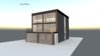
Hi, would be grateful for any info or links to help me with a design for an extension to the rear of a cuboid house.


The extension consists of six brick (clad) pillars (reinforced with steel columns), horizontal beams, a flat roof terrace and sliding doors. Bordering the underside of the roof terrace are black fascia covering joists/insulation/potenially bricks/blocks etc.


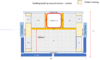
It is this latter bit I am struggling with. I have the design details where you have bricks or blocks behind the fascia tied into the pillars, with these built on a plate welded to the beams (or a premanufactured equivalent).


But is there an option where you simply use, say, a structured, relatively lightweight insulated material to sit above the doors and in front of the beam in an energy efficient manner (ie no cold bridges). Spans are around 3.5m.
 

Attachments

  • SLIDE.jpg
    SLIDE.jpg
    66 KB · Views: 294
Sponsored Links
Sponsored Links
Yes it's the same.

The will normally be some timber noggins fixed into the web to fix the cement board to. There needed to be a strip of insulation/rubber/ plastic between these and the steel to provide a thermal break.
 
Thanks - this is my "extrapolation" expressed as some drawings... Any comments most welcome
Cladding build up around column - central.png
Cladding build up around column - corner.jpg
Cladding build up around column and beam - Plan.png
Cladding build up over door opening - Plan detail.png

Is it OTT to go into this level of detail or can you let a builder "get on with it".
 
Is it OTT to go into this level of detail or can you let a builder "get on with it".
It isn't OTT to go into this level of detail but I wouldn't give 'drawings' like that to a builder, they aren't proper construction drawings and what you are showing as elevations are sections.
 
Your drawings are not detailing how it's all to be fixed together. Basically, that's half a job as the whole idea of detailing is to detail how to make the thing.

Builders are typically not designers. They may be great at standard cavity walls with a lintel on them, but not so great at non standard, non traditional construction ..... so you have to tell them what to do.
 
but not so great at non standard, non traditional construction .....

Yes they are: surely youve seen a builders 'drawing' before.................. they are usually to be found on an offcut of plasterboard, or on the back of a travis perkins receipt. :ROFLMAO::ROFLMAO:
 
Builders are typically not designers. They may be great at standard cavity walls with a lintel on them, but not so great at non standard, non traditional construction ..... so you have to tell them what to do.
Absolutely bang on. The worst builders are those that think they are designers.

I'm currently building a fully supporting bay window (all window and no masonry above sill level) and am waiting for the steel detailing from the SE via the architect. Preliminary sketches from the architect are a bit confusing and contradictory, but we'll get there.
 
Last edited:
Well powerpoint has its limits.... I have someone who will produce proper drawings with the actual design once I've figured out all the details, and share them as pdf or dwg on this site.

So my current thinking on the "how to fix" issue.
  • I'll specify that the blocks of OSB faced PIR be orientated so OSB side face steel and is glued to it, then taped with a suitable tape to hold in place while a surrounding frame is constructed.
  • A wooden frame (19mm x 38mm battens?) will be constructed around the posts, attached to noggins (external side) and joists (internal side) at the top and the floor at the bottom. Ditto above the door openings.
  • Any voids/ cavities to be filled with rockwool insulation or PIR
  • Cement board will be fixed to the wooden frame with drywall screws.
  • Brick slips will be attached with [a suitable adhesive when I find that detail]

Questions that spring to mind
  • Should I aim to connect the framing directly to the post eg glue battens to the steel and use them to link to the framing. Or box in the steel post, gluing and screwing the timber to form a solid structure?
  • Can you/should you drill and use holes to fix to steels?
  • What centres for the horizontal bits of the frames - 600mm?
  • Additional precautions for the bottom of timbers re damp?

sketch around column.png
 

Attachments

  • sketch around column.png
    sketch around column.png
    680 KB · Views: 229
Typical ways of fixing to steels are self drilling screws (aka Tek screws) with an impact gun or some guys use a nail gun. I've never done the latter.
 
Preliminary sketches from the architect are a bit confusing and contradictory

Well architects get paid for drawings not building.......

I generally think architects drawings are a good starting point but often need further working out for the construction to work.

Its a strange industry because almost all domestic extensions are built from building regs drawings which are not dimensioned working drawings.

It doesnt help when architects put reams of cut and paste, non specific building regs blurb on the drawing in a tiny font size.
 

DIYnot Local

Staff member

If you need to find a tradesperson to get your job done, please try our local search below, or if you are doing it yourself you can find suppliers local to you.

Select the supplier or trade you require, enter your location to begin your search.


Are you a trade or supplier? You can create your listing free at DIYnot Local

 
Sponsored Links
Back
Top