
You are using an out of date browser. It may not display this or other websites correctly.
You should upgrade or use an alternative browser.
You should upgrade or use an alternative browser.
Has anyone seen this done before?
- Thread starter ppuch1
- Start date
- Joined
- 11 Jan 2004
- Messages
- 46,400
- Reaction score
- 3,728
- Country

You mean:
http://i122.photobucket.com/albums/o264/ppuch1/Image001.jpg
Sorry! When I tried your link a few minutes ago, it was broken!
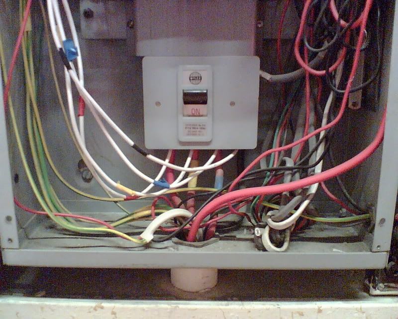
The white wires are????
http://i122.photobucket.com/albums/o264/ppuch1/Image001.jpg
Sorry! When I tried your link a few minutes ago, it was broken!
The white wires are????
you need to remove the [/url] from the end of your link 
It is not unknown when the outgoing tails are the same size as the incommers, but it is still not good practice IMO.
By the looks of the photo the SWA is well undersized for the fuses supplying the DB.
Was the SWA feeding another submains?
It is not unknown when the outgoing tails are the same size as the incommers, but it is still not good practice IMO.
By the looks of the photo the SWA is well undersized for the fuses supplying the DB.
Was the SWA feeding another submains?
I was still logged into photobucket site.
The wires are connected to a DB with 100A main switch which is fed from a main 200A switch. It also has another 2 DB's
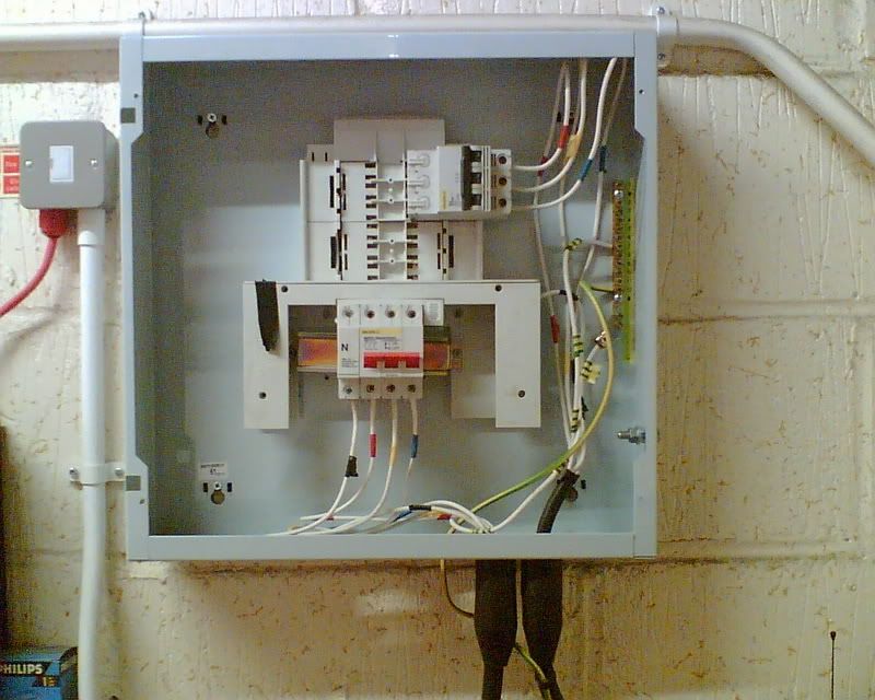
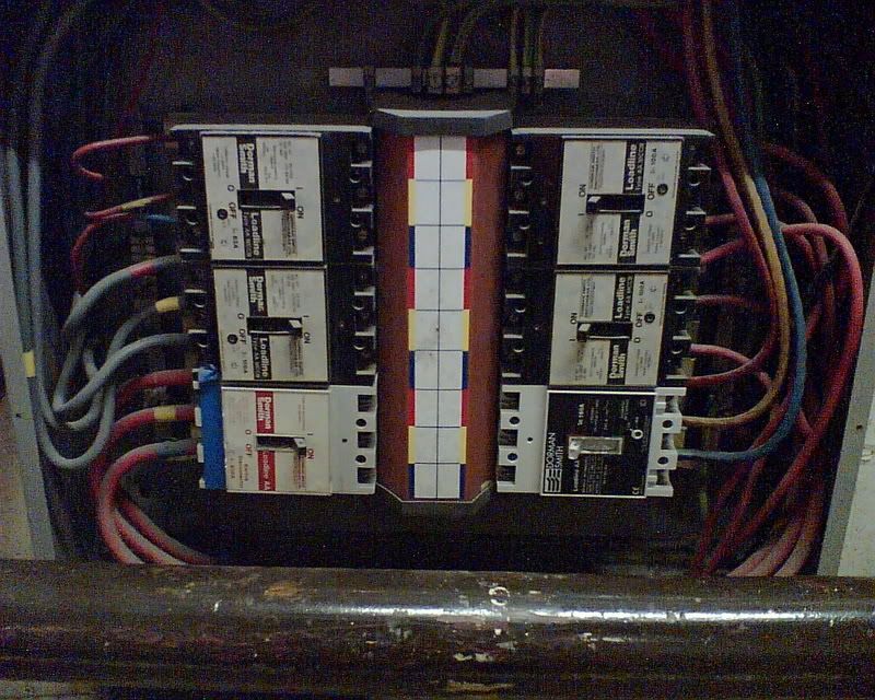
Yes RF , the white wires are to supply a sub DB (with 125A main switch)that supplies power to an outside cabinet for a mobile chiller unit. They are the RYB phase terminals to this new 3 phase DB as shown below...
I thought this was not the way to do it. Surely they should be run from a dedicated TP fuse on the bus bar of the original fuse board.
I cannot see a way of isolating the tails unless you switch off the main board prior to the board they are spliced in with.
The wires are connected to a DB with 100A main switch which is fed from a main 200A switch. It also has another 2 DB's
Yes RF , the white wires are to supply a sub DB (with 125A main switch)that supplies power to an outside cabinet for a mobile chiller unit. They are the RYB phase terminals to this new 3 phase DB as shown below...
I thought this was not the way to do it. Surely they should be run from a dedicated TP fuse on the bus bar of the original fuse board.
I cannot see a way of isolating the tails unless you switch off the main board prior to the board they are spliced in with.
So the white wires are currently fused at 100A? And they are how big? This stinks of people touching what they should not be touching (I'm not getting at you btw). Personally I'd be tempted to notify the client in writing that this installation is not safe and advise its immediate isolation.
Few issues at stake here, the cable is probably not protected by the upstream breaker from fault current (need to check the maths - see below) and there is little to stop someone adding another 3 phase breaker in the board (although they should really also check the 100A supply is adequate). Are the banjos also present and earthed? Is there an EIC for this (or is that a daft question!!) Is it an industrial or commercial environment?
What is the efli at the square D board, SWA size and type, protective device on the supply type and size?
I know what you mean Spark123, although I now have a little bit of experience it still surprises me how much people do get away with. This is a commercial install - a large well known frozen food Co - and no paperwork as far as I can find out.
It has been isolated (switched off) and a big label put on the cabinet... see picture... telling them NOT to use it until it has been rectified, which we are going to quote for. It has been escalated to my boss who is our NIC rep and he is going to look into this.
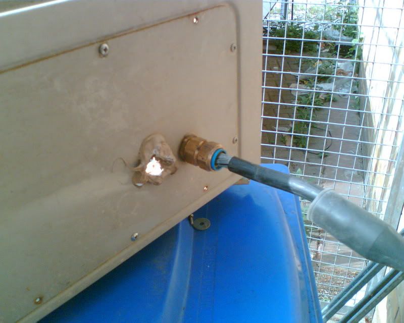
For info, the cable size is 5x 4mm armored (didn't make a note of the type) No banjos or earthing at both ends of SWA...see picture.
I did a loop test at the end of cct and got 0.26 ohm as highest reading.
protective device on supply side is 100A mccb (Dorman Smith) see picture... middle left switch.
Haven't worked out any calcs for Fault Current yet. but you can bet that it probably wont comply.
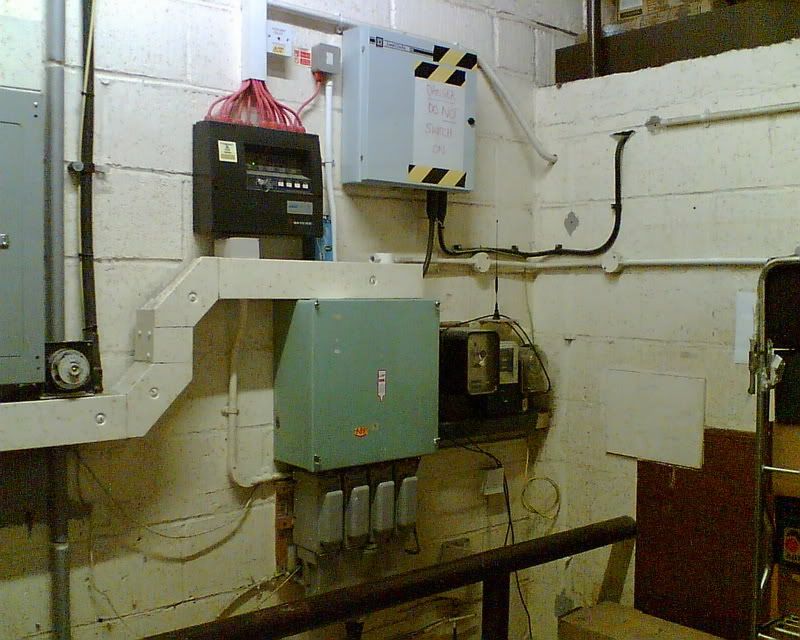
It has been isolated (switched off) and a big label put on the cabinet... see picture... telling them NOT to use it until it has been rectified, which we are going to quote for. It has been escalated to my boss who is our NIC rep and he is going to look into this.
For info, the cable size is 5x 4mm armored (didn't make a note of the type) No banjos or earthing at both ends of SWA...see picture.
I did a loop test at the end of cct and got 0.26 ohm as highest reading.
protective device on supply side is 100A mccb (Dorman Smith) see picture... middle left switch.
Haven't worked out any calcs for Fault Current yet. but you can bet that it probably wont comply.
You'll need to find out the max Zs for a 100A MCCB, not really my area I'm afraid, maybe someone else will know? Also check a 4mm is suitable for the amount of energy let through by the MCCB.
Is it a viable option (providing you have permission) to disconnect the 4mm from the supply at the Wylex board?
Is it a viable option (providing you have permission) to disconnect the 4mm from the supply at the Wylex board?
The OP is going to have to track down the data sheets for the MCCB, going to need the time/current chart for the Zs, and the I²t / time graph (I suppose you could do fault level squared and multiply it by the stated operating time, but that may be a little bigger than the real life value)
I beleieve the 17th is going to include time/current curves for MCCBS
I beleieve the 17th is going to include time/current curves for MCCBS
or just trust his gut feeling that it won't comply.
Even if it does comply on those grounds that 3 phase board is just asking for a HVAC tech to stick another breaker in.
The obvious would be to move one of the smaller circuits on the dorman smith board to the new board and then make the new board into a proper submain.
Even if it does comply on those grounds that 3 phase board is just asking for a HVAC tech to stick another breaker in.
The obvious would be to move one of the smaller circuits on the dorman smith board to the new board and then make the new board into a proper submain.
Thanks for your input guys... all very interesting and gives me something to work on.
Perhaps I should have shown this pic earlier...
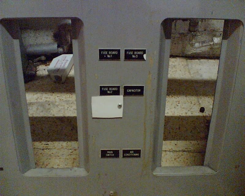
The whole install is fairly full and probably loaded to its max (I will try to do some load tests on next visit) so as you will see from the panel labels all the MCCB's are being used for high loads or stuff that cannot be moved/changed.
I still believe that the white 4 core should not have been installed this way at all. And I will try to make sure they get it removed and installed correctly. I will see also make sure they do not use the sub board until it has all been corrected.
Incidentally I remember hearing that this site had a fire due to overloading a while ago, so I shall try and find out more about that incident which might give me more power (pardon the pun) to get this condemned!
Perhaps I should have shown this pic earlier...
The whole install is fairly full and probably loaded to its max (I will try to do some load tests on next visit) so as you will see from the panel labels all the MCCB's are being used for high loads or stuff that cannot be moved/changed.
I still believe that the white 4 core should not have been installed this way at all. And I will try to make sure they get it removed and installed correctly. I will see also make sure they do not use the sub board until it has all been corrected.
Incidentally I remember hearing that this site had a fire due to overloading a while ago, so I shall try and find out more about that incident which might give me more power (pardon the pun) to get this condemned!
DIYnot Local
Staff member
If you need to find a tradesperson to get your job done, please try our local search below, or if you are doing it yourself you can find suppliers local to you.
Select the supplier or trade you require, enter your location to begin your search.
Please select a service and enter a location to continue...
Are you a trade or supplier? You can create your listing free at DIYnot Local
Similar threads
- Replies
- 8
- Views
- 3K
- Replies
- 7
- Views
- 948