
No, that's much the same as your previous one, and also a weld failure! I can see I'm going to have to draw something, but will have to do so later tonight.Any closer

You are using an out of date browser. It may not display this or other websites correctly.
You should upgrade or use an alternative browser.
You should upgrade or use an alternative browser.
Help with crimping
- Thread starter pjo123
- Start date
OK - as you say, it's not that much different from the previous one (except it's not split), but I wondered if it was perhaps moving in the right direction. The problem, and what is rather surprising, is that if one does Google Image searches, most of what one finds looks like one or other of the pics I've posted, invariably described as a 'satisfactory crimp'!No, that's much the same as your previous one, and also a weld failure! I can see I'm going to have to draw something, but will have to do so later tonight.Any closer
Kind Regards, John.
Yes, I'm probably being too picky. Both those samples would be satisfactory electrically, and would probably pass a pull test. To be honest I suspect that a cold weld will be made at various points along the compressed part of the conductor so a section at any point won't show a full cold weld. The same principle was used in wire-wrap joints on early mainframe computers where there were 20 points of contact per joint so enough were likely to be good.
Is this what you have in mind? It's 16mm2.
I know the insulation is not correct. I only did it for the picture. View media item 35094 View media item 35095
I know the insulation is not correct. I only did it for the picture. View media item 35094 View media item 35095
Yes, I agree with all of that. What I'm pondering is what either of those piccies (or any others like them) would have looked like had it been a solid conductor that had been crimped.Yes, I'm probably being too picky. Both those samples would be satisfactory electrically, and would probably pass a pull test. To be honest I suspect that a cold weld will be made at various points along the compressed part of the conductor so a section at any point won't show a full cold weld. The same principle was used in wire-wrap joints on early mainframe computers where there were 20 points of contact per joint so enough were likely to be good.
Kind Regards, John.
EFL, yes, thanks, that's the sort of thing I meant. Failed according to BS 7609 though!
Why would you want one side to be crimped less tightly than the other?
Because most insulated crimps , have a recess for the insulation to enter, the lesser crimp does that bit and the heavier crimp does the barrel and conductor
Wouldn't that look much like the second pic I posted if it were sectioned through the indent?EFL, yes, thanks, that's the sort of thing I meant. Failed according to BS 7609 though!
Kind Regards, John.
I don't think so. I think the example in your picture is more 'folded in' along the seam for a certain distance rather than 'punched' as is mine.Wouldn't that look much like the second pic I posted if it were sectioned through the indent?.
That's true, but the shape one sees in section is obviously a function of the size and shape of the 'blunt spike' producing the indent - so I thought that something conceptually similar to that which produced yours may have result in the picture.I don't think so. I think the example in your picture is more 'folded in' along the seam for a certain distance rather than 'punched' as is mine.
Whatever, unless I haven't been looking carefully enough, I haven't seen any of the currently widely-available crimpers (in that £11-£70 range) which seem to have such an 'indenting device', have you?
Kind Regards, John.
I haven't.
What I was thinking of - your picture - is more prevalent on small wires which come prefitted with the connector; as in car wiring where the crimp ends up looking like two adjacent tubes.
I imagine this would take a lot of force and precision.
What I was thinking of - your picture - is more prevalent on small wires which come prefitted with the connector; as in car wiring where the crimp ends up looking like two adjacent tubes.
I imagine this would take a lot of force and precision.
Good point - particularly in relation to the first pic I posted; maybe that's what it was. As for the force needed, I would imagine that factory-fitted ones are probably produced by a serious press, not a hand tool.I haven't. ..... What I was thinking of - your picture - is more prevalent on small wires which come prefitted with the connector; as in car wiring where the crimp ends up looking like two adjacent tubes. I imagine this would take a lot of force and precision.
Kind Regards, John.
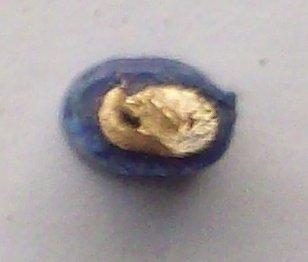
OK, not a brilliant photo (will try again later in the week with a more appropriate camera), and some consequences of he hacksaw, but this is a section through a crimp I made today, of a 2.5mm² solid conductor in a blue insulated crimp, made with the TLC ratchet crimpers which BAS frequently promotes. I think even the poor pic shows some 'issues', although there could be a cold weld there:
It looks to me as if the fact that conductor did not fill the hole in the crimp has allowed the left hand side (as viewed) of the crimp to collapse and split under compression, not to mention some lateral voids into which I suspect that creepage might occur over time. However, the last thing I would claim to be is a metallurgist or authority in these matters, so any comments would certainly be welcome!
Kind Regards, John.
the TLC ratchet crimpers which BAS frequently promotes.
Use a crimper LIKE this:

.
.
.
.
Use a crimper LIKE this:the TLC ratchet crimpers which BAS frequently promotes.
http://www.tlc-direct.co.uk/Images/Products/size_3/DVDHCR15.JPG[/QUOTE]
Yep, that's the one.
Kind Regards, John.
DIYnot Local
Staff member
If you need to find a tradesperson to get your job done, please try our local search below, or if you are doing it yourself you can find suppliers local to you.
Select the supplier or trade you require, enter your location to begin your search.
Please select a service and enter a location to continue...
Are you a trade or supplier? You can create your listing free at DIYnot Local
Similar threads
- Replies
- 23
- Views
- 10K
T