HF Dimmable LED Ballast - pins in.

Joined
30 Oct 2008
Messages
114
Reaction score
0
Location
Berkshire
Country
United Kingdom
I have asked my [friendly] electrician to fit a dimmable LED ballast with dimmable LED T8 tubes to two T8 batons. His time is money and I prefer to pay him for doing the practical stuff I need as opposed to all the theory and questions which I prefer to understand myself.

I am just wondering if I have done the wrong thing and bought the wrong ballast.

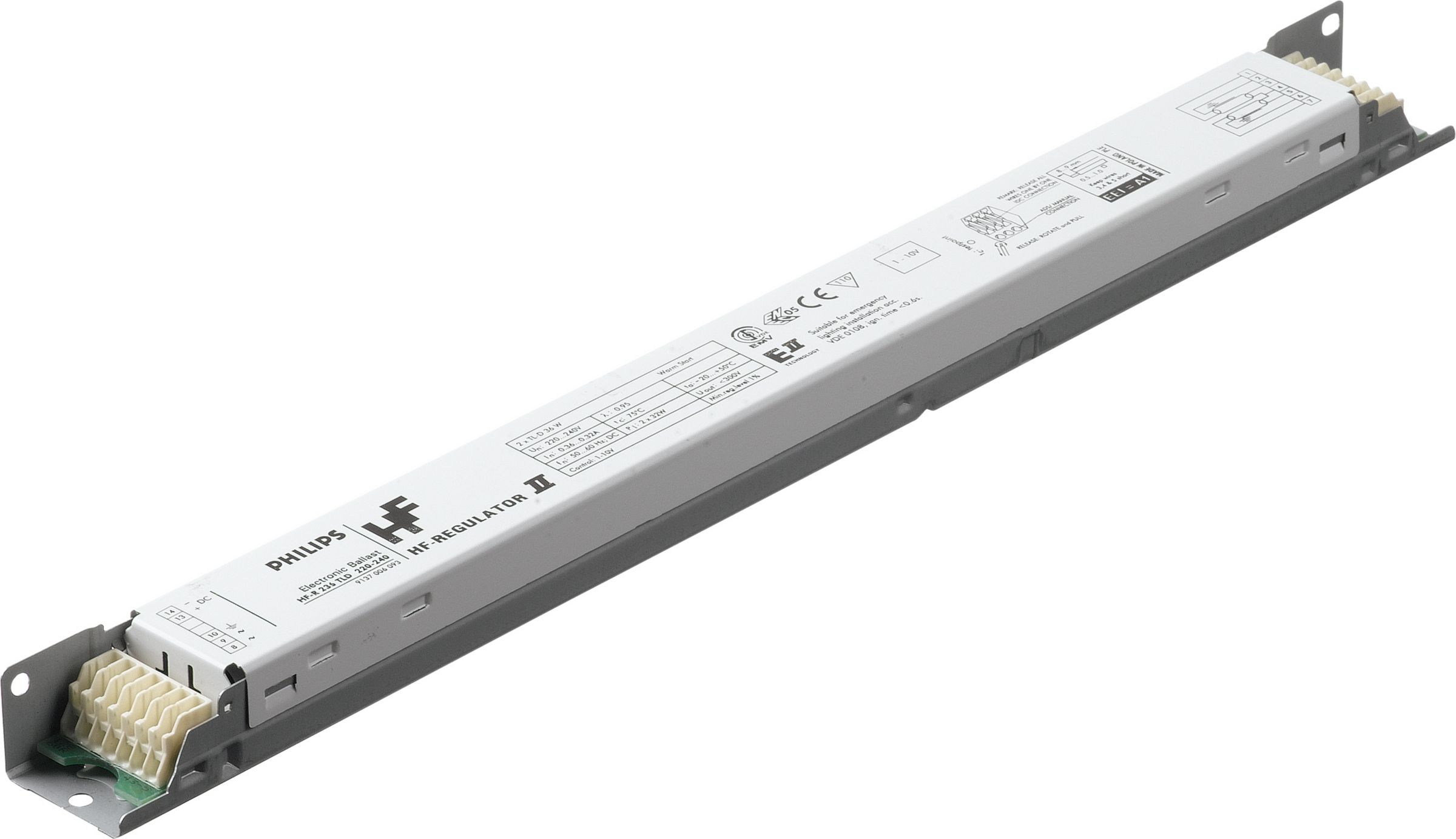
On the ballast I am intending him to fit, it has four output pins 4,5,6,7 which the [very poor] circuit diagram shows two connected to each end of the tube. Seems pretty simple. However on the input side there are three pins bunched together with an earth symbol 8,9,10 and two separately showing DC + - 14,13.

diag.jpg


(I feel pretty sure the three bunched together would be the standard 230v 5A AC input. The manufacturer [Phillips] state that the ballast accepts a 230v input.)

Does this mean this ballast can take input power from AC 230v and DC as well or is the DC part for something entirely different ?

Thanks in advance.
 
Sponsored Links
That wiring diagram is for an HF fluorescent tube ballast with optional DC input for a 1-10V dimmer controller.
It's of no use with any LED tube.

LED tubes do not require any external ballast or drivers, they are self-contained devices.
 
Ah . . . many thanks.

So for this tube, no ballast is needed, just the standard trailing edge dimmer ?
It says dimmable, "depends on ballast" in its specs - which is where I guess my understanding probably went off tracks.
 
Sponsored Links
The LED tubes I bought had switch mode power supplies built in so it would auto compensate for any volt drop across a wire wound ballast (choke) so any attempt at dimming would not work. The one you have linked to is however designed for a HF ballast not a wire wound, and it does say "Dimmable Yes – Check ballast compatibility" it also says
1704744165004.png
and says
1704744241152.png
So it seems down to the ballast, and we have no details about that, as @flameport says the DC may be for dimming control, or it could be as I thought for emergency use, but I would not be trying to use a ballast designed for fluorescent with a LED tube unless I had some thing like a theatre with loads of dimming fluorescents already fitted. It is clearly a special tube, and it may work, but not really worth the hassle unless you already have loads fitted.
 
Ok.

I did check this compatibility sheet (p35) to ensure this ballast “HF-R 158 TLD EII” would work and the diagram in the first post was its wiring diagram. It is specified as the only compatible dimmable ballast for that tube and specified as AC input. Which is the reason for my confusion and my question/post here. I guess the DC input is for emergency power as it can be used for emergency lighting, I am hoping it’s not a DC control input for dimming otherwise it’s return time….
 
Last edited:
So for this tube, no ballast is needed, just the standard trailing edge dimmer ?
Unclear.
Claims it can be used at high frequency.
Presumably designed for retrofit into a certain type of existing fitting.

In most cases shoving LED tubes into places where fluorescent tubes once were is something to be avoided.
If you want LED lights, then buy a complete new fitting designed for the purpose.

this ballast “HF-R 158 TLD EII”
Electronic ballast for fluorescent lamps with dimming via 1-10V control signal.
 
Thanks very much for your help guys.

The whole point is to avoid costly redecoration [again] which was recently completed. So no fitting changes or wall damage allowed.
Fitting an additional wire for the dimmer circuit is therefore out.

I'll return this and get him to fit the voltcon triac offering which I had seen but did not really want the beam angle in those tubes, but I'll live with it.
 
Some thing seems wrong
1704805949518.png
how can the voltage be 36-42 volt DC when the line frequency is 50/60 Hz? I note one has to select options, so maybe 3 different tubes
1704806338176.png
but I hope some one can work it all out, maybe @flameport can, but it looks like double Dutch to me.
 
I have very recently fitted 22 LED DALI dimmable fittings and the circuit was basically this:
Ignore any numbers
1704823621901.png

And as mentioned the DC terminals are for remote 0-10V dimming which works slightly differently to stage lighting 0-10V dimming.
 

DIYnot Local

Staff member

If you need to find a tradesperson to get your job done, please try our local search below, or if you are doing it yourself you can find suppliers local to you.

Select the supplier or trade you require, enter your location to begin your search.


Are you a trade or supplier? You can create your listing free at DIYnot Local

 
Sponsored Links
Back
Top