I am trying to make a fan, how big should it be?

A 4 stroke motorbike engine might just work as long as you turn it slowly enough. A friend of mine used to make compressors out of them. Alternatively you could break into the scrap heap they use for "Scrapheap Challenge". It always seems to contain exactly what's needed.

Now about these cogs... They wouldn't look like this would they?
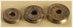
If so they're definitely pulley wheels
 
Sponsored Links
you want something like the mythbusters made to test the "sucked up diver" myth..
they put an outboard engine on the end of a shaft in a 12 inch pipe and it moved like 200 litres a second ..
 
I like the idea of using the cylinders from an old petrol engine. He'll just need to readjust the timing and tappets to ensure that the vlave open at exactly the right time so that there's no compression of the water going on.

Another, nearly free solution would be it there's a manhole anywhere within reach, which is deeper than the pond. Then the op could use several hosepipes simultaneously, using syphons
 
Many thanks for all your replies

Much appreciated

I think a modified sump pump is what I need

What I wanted to do originally was to have a device that sits on the lawn and then a short hose that went into the pond. Then I switch on the device sitting on the lawn and a fan spins really fast pulling air from vents in the device and then somehow create blow back which creates an air channel that is strong enough to pull water through the hose, and exit through a split in the hose that branches off to another hose that leaks the water out on to the lawn, is this possible?

I have not done many projects before and so this is quite new to me. I have dealt with some basic circuits using a breadboard, I am an fast learner. I would like to make quite a complex circuit now and first do so using a simulator where I can test it works. Do you know of any free breadboard simulators where can I use the 555 timer IC?

I was using the free java breadboard simulator which I think is superb and easy to use. It just does not have the 555 timer chip which is annoying.

Anyway I managed to get a picture of what this cog I am talking about looks like, http://img24.imageshack.us/img24/4043/junebugmongoose.th.jpg

You see that device on the right, and those orange things which look circular, well that is what I call a cog I believe that's the correct name. That's not exactly what I am after still, my cog which I remember is like that but has a rim to hold things in place such as string. I hope you understand.
 
Sponsored Links
The triple five is ancient. I used to use it when I was a kid. I don't really see how you can use it with what you are doing. How would you interface it with your pump?
 
The triple five is ancient. I used to use it when I was a kid. I don't really see how you can use it with what you are doing. How would you interface it with your pump?

The pump is for another thing I am making, nothing to do with the electronics for the breadboard project.
 
suicide-bear.jpg


I think you need to start a separate thread again for each of your 'ideas' and explain a little better exactly what it is you are trying to achieve. ;)
 
Having been the first (encouraging) respondent to this thread, I must admit to missing most of it but it’s now gone beyond me. Most (if not all) of my original thoughts on the technicalities have already been covered but I think “Freds Ted” says it all; I’ve got to agree in the nicest possible way that you are either a complete & total nutter or a bored regular taking us all for a rather amusing ride :LOL:
 
vacuum transfer of materials utilising a gravity discharge system is a real posibility.. they use it for transferring things like tights from one production section to another..

you'd need a sweeping tee and the tee would have the suction on the straight through with the discharge on the tee.
the tee should sweep towards the pond..
Would you care to sketch that out?
 
View media item 14855
your vacuum would need to be higher than the pond though in case the water takes the wrong turn.
try it with waste pipe and a wet/dry vacuum cleaner on the end..

the "flap valve" needs to be weighted so that it is held near closed so the vacuum sucks it shut until the water weight pushes it open..
the "breather holes" are needed so that the water won't just go straight to the vacuum cleaner..

a section of the same pipe cut lengthways and slipped over the breather holes allow you to "tune" it to the right suction.. same as on some vacuums..
Cunning plan CJ.
 

DIYnot Local

Staff member

If you need to find a tradesperson to get your job done, please try our local search below, or if you are doing it yourself you can find suppliers local to you.

Select the supplier or trade you require, enter your location to begin your search.


Are you a trade or supplier? You can create your listing free at DIYnot Local

 
Sponsored Links
Back
Top