Internal Sounder Wiring Issue

Joined
4 Oct 2019
Messages
19
Reaction score
0
Location
United Kingdom
Country
United Kingdom
Hi,

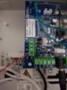
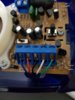
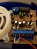
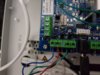
I'm attempting to write an internal sounder to a Honeywell Galaxy FX020 control panel and I want to wire the strobe and the sounder independently rather than make a link from the sounder terminal to the strobe terminal.

But it seems I can only wire one of the terminals and not both together...

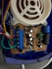
The sounder is a CQR Piccolo Internal Sounder. I've uploaded screenshots of the terminals and the manual for the piccolo sounder
 

Attachments

  • 20191114_183820.jpg
    20191114_183820.jpg
    216.4 KB · Views: 368
  • 20191114_183810.jpg
    20191114_183810.jpg
    181.8 KB · Views: 365
  • A4-piccolo_instructions_grade_3_issue-5 (2).pdf
    238.3 KB · Views: 382
Sponsored Links
OP 1 is the Sounder trigger, so connect that to the S terminal.
OP2 is the Strobe terminal, so connect that to the F terminal.
Connect the -VE (C) terminal to the 0V terminal at the panel.
In the sounder, connect -VE(C) with a link wire to one of the tamper terminals.
Connect the second tamper terminal in the sounder back to the -T at the panel.
Unfortunately that hasn't worked out as I thought it would, when the alarms goes off I hear a popping/crackling sound from the sounder
 
So after hours of faffing around with the sounder I managed to make a link to the sounder to make the flash and sounder work together but I still want to make the sounder and strobe run independently. Is it even possible?
 

Attachments

  • 20191116_220544.jpg
    20191116_220544.jpg
    163.8 KB · Views: 277
  • 20191116_220501.jpg
    20191116_220501.jpg
    222.2 KB · Views: 370
Sponsored Links
Hi @LordWaycrest,

So to confirm, you’ve tried GalaxyGuy’s terminations and, following your original sounder picture, have wired as follows:

Sounder-
S - Blue
F - Red
C - Black
T1 - Small link back to Sounder ‘C’ terminal
T2 - Green

Panel-
OP1 - Blue
OP2 - Red
0v - Black
T- - Green

Assuming this is what you did, when you say there is a popping/crackling sound. Is this when in an alarm status? Is the strobe also activated?
Have you tested the outputs independently from the output test menu and still see the same result?
Yep :(
 

Attachments

  • 15741046209654005805822266920155.jpg
    15741046209654005805822266920155.jpg
    210.8 KB · Views: 400
  • 15741046507622044089007532233364.jpg
    15741046507622044089007532233364.jpg
    186.2 KB · Views: 434
According to the installation manual op1 and op2 are switched negatives

For you to be able to wire it how you want they need to be switched positives which is of course not the case.

I'm currently at a loss as to how to get around the problem , sorry
 
Actually the only thing I can think of at mo which I'm sure you've already thought of, is to have a separate strobe and sounder
 
I would have to look at the manuals and work it out.

what do you want to achieve, what have you got that your happy with and what have you got that your not happy with.

Galaxyguy is the galaxy expert
 
There you go sparkymarka has solved it.

Wire it as per galaxyguy
Reverse polarity as per sparkymarka

Should then work exactly as you want it
 
Also, if you have positive triggers (programmed positive as per above comments), then you need to ensure the pull up jumpers are fitted. This will ensure the trigger jumps to +12v.
 
The flex has open collector outputs with jumper links to connect the collector of the output transistor to a pull up resistor. The little black jumpers are on the pcb just behind the output screw terminals.

The jumpers are only left in the open state when the connected device has its own pull up, which may have a different voltage level. In most cases for alarm Sounders, the jumpers can be left fitted.
 

DIYnot Local

Staff member

If you need to find a tradesperson to get your job done, please try our local search below, or if you are doing it yourself you can find suppliers local to you.

Select the supplier or trade you require, enter your location to begin your search.


Are you a trade or supplier? You can create your listing free at DIYnot Local

 
Sponsored Links
Back
Top