You should e able to get it working now.

You are using an out of date browser. It may not display this or other websites correctly.
You should upgrade or use an alternative browser.
You should upgrade or use an alternative browser.
Internal Sounder Wiring Issue
- Thread starter LordWaycrest
- Start date
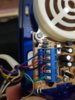
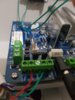
I've changed the output polarity from 0=POS to 1=NEG and wired the sounder to the panel as shown in the images, left the jumpers in and still getting the pop sound when the sounder is supposedly active, it also pops again when the sounder is off.The flex has open collector outputs with jumper links to connect the collector of the output transistor to a pull up resistor. The little black jumpers are on the pcb just behind the output screw terminals.
The jumpers are only left in the open state when the connected device has its own pull up, which may have a different voltage level. In most cases for alarm Sounders, the jumpers can be left fitted.
Attachments
- Joined
- 31 Oct 2019
- Messages
- 1,423
- Reaction score
- 225
- Country

Have you got a multimeter?
I do not :/Have you got a multimeter?
- Joined
- 31 Oct 2019
- Messages
- 1,423
- Reaction score
- 225
- Country
Does the strobe work?
Yes if I apply 12v to the F terminal and connect the 0v to the C terminal.Does the strobe work?
- Joined
- 31 Oct 2019
- Messages
- 1,423
- Reaction score
- 225
- Country
You need to check you are getting 12v at op1 and op2,
Think you can eliminate the sounder being the issue as you can get that working when you supply it with 12v
Multimeters are not that expensive and are a useful fault finding tool
Think you can eliminate the sounder being the issue as you can get that working when you supply it with 12v
Multimeters are not that expensive and are a useful fault finding tool
I'll look into getting one, I also want to say that I managed to wire a kinetic external sounder to the outputs and it worked good as gold, I'm really confident it is the sounder not being compatibleYou need to check you are getting 12v at op1 and op2,
Think you can eliminate the sounder being the issue as you can get that working when you supply it with 12v
Multimeters are not that expensive and are a useful fault finding tool
- Joined
- 31 Oct 2019
- Messages
- 1,423
- Reaction score
- 225
- Country
It is possible
It looks to me like you're not getting 12v at op1 or op2 for some reason , if you can get 12v at them there is no reason why this sounder should not work.
Hopefully galaxyguy might have a trick up his sleeve....
It looks to me like you're not getting 12v at op1 or op2 for some reason , if you can get 12v at them there is no reason why this sounder should not work.
Hopefully galaxyguy might have a trick up his sleeve....
I can wire the sounder to the output but I have to wire the F terminal (strobe) to 12v (panel) on the control panel then wire the C terminal (sounder) to the 0v (panel) and make a link from the S terminal to the F terminal in the sounder, but I want the strobe and sounder to run independentlyIt is possible
It looks to me like you're not getting 12v at op1 or op2 for some reason , if you can get 12v at them there is no reason why this sounder should not work.
Hopefully galaxyguy might have a trick up his sleeve....
- Joined
- 31 Oct 2019
- Messages
- 1,423
- Reaction score
- 225
- Country
I can wire the sounder to the output but I have to wire the F terminal (strobe) to 12v (panel) on the control panel then wire the C terminal (sounder) to the 0v (panel) and make a link from the S terminal to the F terminal in the sounder, but I want the strobe and sounder to run independently
Which you can do by getting 12v at op1 and op2
However it doesn't appear that you are at present cause if you were the sounder and strobe would work, without a multimeter however there's no way of telling
Just tested the outputs with a muti meter and I'm getting 12v from the outputs, so I'm going to assume the sounder is at fault.
DIYnot Local
Staff member
If you need to find a tradesperson to get your job done, please try our local search below, or if you are doing it yourself you can find suppliers local to you.
Select the supplier or trade you require, enter your location to begin your search.
Please select a service and enter a location to continue...
Are you a trade or supplier? You can create your listing free at DIYnot Local
Similar threads
- Replies
- 6
- Views
- 7K
- Replies
- 1
- Views
- 5K