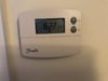
It would appear that the hot water is heated directly by the combi boiler, so doesn't need any time control, and that you have two heating zones, each with their own programmable thermostat. What follows is based on that assumption. The existing room thermostats look like a Danfoss TP4000's is that correct?
If they are TP's, then you will need two Single Channel Hive's, one for each heating zone.
Inside the TP there will be be two wires connected to terminals marked (2) 'COM' and (3) 'NO'
They should be rerouted to the Hive single channel receiver terminals marked unsurprisingly (1) 'Common' and (3) 'NO'
You will probably find that the thermostat wires are black and brown and go to these terminals.
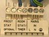
One thermostat should have its black wire in 7 and the other 6. Once you have determined this, you could disconnect the existing thermostat wires here and connect the wires from Hive receiver 'Common' and 'NO' in their place.
So:
For one stat - Hive receiver 1 'Common' goes to the terminal where the brown wires are, and the 'NO' wire goes in terminal 7
For the other stat - Hive receiver 2 'Common' goes to the terminal where the brown wires are, and the 'NO' wire goes in terminal 6
The existing thermostats are battery operated, but the Hive receivers are mains operated, so a 230v mains supply needs to be connected to N & L to provide them with operating power. This mains supply should come via the 3A fused spur that supplies the boiler. It can be connected at any convenient point,
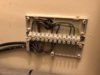
However, looking at your junction box, the second terminal from the left with the blue wires from the motorised valves and the grey wire, can provide the N, and for the L simply insert a link at each Hive receiver to join terminals (1) 'Com' and (L) 'Permanent Live' together.
You may find when you have finished, that the thermostats work in reverse, Zone 1 thermostat operates Zone 2 heating and vice versa. If that does happen simply swap the two brown wires going to the motorised valves in the bottom of terminals 6 & 7 over.
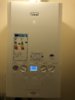
I see that you have opened up the boiler casing to photograph the boiler wiring terminals, nothing needs to be done there, however, to get to the terminals in some Ideal boilers, you have to open up a room sealed compartment to access them. This is not DIY and should only have been done by an RGI (Gas Safe) who can carry out the necessary safety checks to make sure that the boiler is safely sealed up again afterwards.